
 Personal Account


 Личный Кабинет

Plasma spraying plant "UPU-12USP"

Plasma spraying plant "UPU-12USP"
Description
Plasma spraying plant "UPU-12USP" for applying of coatings via plasma spraying method
 Detailed information PDF

1. Purpose.
The "UPU-12USP" plasma spraying plant is designed for applying of metal and ceramic powder materials to the surfaces of products via the plasma spraying method and allows you to apply wear-resistant, corrosion-resistant, friction, insulating and other special coatings simultaneously from two powder dispensers.
Coatings are applied using the "UPU-12USP" plant via a plasma jet by depositing particles of the sprayed material onto the product, introduced into the plasma jet in the form of a powder.
When colliding with a product, particles that are in a molten or plastic state are deformed and embedded in the micro-irregularities of the product or plastically deform it with the formation of common points of physical and chemical interaction, ensuring adhesion strength and coating density. The formation of a coating layer of the required thickness is carried out by layer-by-layer spraying when moving the plasma torch relative to the sprayed surface.
2. Features of the physical processes used.
Technological capabilities have been expanded through the use of two dispensers, which allows you to change the nature of the powder, spray with a mixture of two powders, and carry out a continuous spraying process by switching from one dispenser to another.
The quality of deposition has been improved by varying the amount of energy input into the plasmatron (by changing the current and voltage).
The service life of the cathode and anode of the plasma torch has been increased due to a smooth increase in current after excitation of the arc, the ability to operate at low (<315 A) currents, at increased (180 V) voltages and the use of bidistillate for cooling the plasma torch.
3. Technical description. Design features. Equipment advantages.
The "UPU-12USP" plant includes:
- Noise-proof chamber;
- Plasmatron P2;
- Powder supply system;
- Rotator;
- Cooling system:
- Autonomous cooling system (chiller option)
- Pater cooling system for plasma torch
- Powder sifting module;
- Drying cabinet;
- Control system;
- Rectifier model “VPN-650”;
- Gas and electrical distribution.

Noise-proof chamber

Plasmatron P2

Powder dispenser
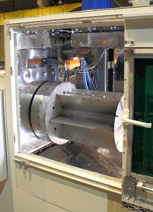
Rotator

Power source "VPN-650"
The "UPU-12USP" plasma spraying plant is designed for applying of metal and ceramic powder materials to the surfaces of products via the plasma spraying method and allows you to apply wear-resistant, corrosion-resistant, friction, insulating and other special coatings simultaneously from two powder dispensers.
Coatings are applied using the "UPU-12USP" plant via a plasma jet by depositing particles of the sprayed material onto the product, introduced into the plasma jet in the form of a powder.
When colliding with a product, particles that are in a molten or plastic state are deformed and embedded in the micro-irregularities of the product or plastically deform it with the formation of common points of physical and chemical interaction, ensuring adhesion strength and coating density. The formation of a coating layer of the required thickness is carried out by layer-by-layer spraying when moving the plasma torch relative to the sprayed surface.
2. Features of the physical processes used.
Technological capabilities have been expanded through the use of two dispensers, which allows you to change the nature of the powder, spray with a mixture of two powders, and carry out a continuous spraying process by switching from one dispenser to another.
The quality of deposition has been improved by varying the amount of energy input into the plasmatron (by changing the current and voltage).
The service life of the cathode and anode of the plasma torch has been increased due to a smooth increase in current after excitation of the arc, the ability to operate at low (<315 A) currents, at increased (180 V) voltages and the use of bidistillate for cooling the plasma torch.
3. Technical description. Design features. Equipment advantages.
The "UPU-12USP" plant includes:
- Noise-proof chamber;
- Plasmatron P2;
- Powder supply system;
- Rotator;
- Cooling system:
- Autonomous cooling system (chiller option)
- Pater cooling system for plasma torch
- Powder sifting module;
- Drying cabinet;
- Control system;
- Rectifier model “VPN-650”;
- Gas and electrical distribution.
Noise-proof chamber
Plasmatron P2
Powder dispenser
Rotator
Power source "VPN-650"
Technical data
Installed power, kW
120
Plasmatron power, kW
25±10%
Operating current range, A
(100-700) ±10%
Operating voltage range on the plasma torch, V
25-70
Current stability, %
3.0
Powder dispensers, pcs.
2
Dispenser capacity, m3
45*10-4 ±10%
Maximal capacity of powder supply by dispenser, kg/h
5-20
Double-distillate volume in the plasmatron cooling system, m3
0.15
Plasma-forming and transporting gases
argon, nitrogen
Plasma-forming gas consumption, m3/s
5*10-4-83*10-5
Transport gas consumption, m3/s
33*10-6-25*10-5
Gas pressure at the outlet of the reducer, Pa (kgf/cm2)
5*105 (5)
Overall dimensions, mm (L*W*H)
3500*1500*3000
Detailed information PDF
Submit an inquiry
Прошлое
Настоящее
Будущее