
 Personal Account


 Личный Кабинет

Elevator vacuum furnace “PEV-1300-13” for heat treatment

Elevator vacuum furnace “PEV-1300-13” for heat treatment
Description
Elevator vacuum furnace "PEV-1300-13" for heat treatment of parts with quenching in oil or gas
 Detailed information PDF
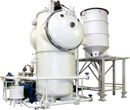
The elevator vacuum furnace "PEV-1300-13" is designed for heat treatment of parts with quenching in oil or gas.
The elevator vacuum furnace "PEV-1300-13" consists of the main units:
- Heating chamber,
- Vestibule chamber,
- Loading device,
- Oil quenching chamber,
- Vacuum system,
- Gas system (gas cooling system),
- Water cooling system,
- Pneumatic system,
- Electrical wiring,
- Power cabinet,
- Control cabinet,
- Operator cabinet.
The furnace operates by heating the workpiece in a vacuum to a certain temperature and performing heat treatment of parts with quenching in oil or gas.
Structurally, the furnace is made in the form of a vertical vacuum chamber consisting of a heating chamber, a middle chamber (vestibule) for loading/unloading products and gas quenching, and a lower chamber - an oil quenching chamber.
A heating section with tape heaters and current leads, busbar leads, and screen thermal insulation is installed in the heating chamber body. Thermocouples are introduced into the heating chamber. The heating chamber has a vacuum lock.
A vacuum system is connected to the heating chamber. The vacuum system is designed to create a vacuum in the chamber volume, has a forevacuum and high-vacuum section.
The lower chamber is designed for quenching the product in oil. The oil quenching chamber has an oil system, which consists of a heat exchanger, an oil pump, a filter, an oil receiver and pipelines.
The gas cooling system provides a gas quenching mode. The system is equipped with a fan, heat exchangers, gas fittings, a receiver and a ramp with gas cylinders.
The water cooling system is designed to supply and drain water required for cooling the vacuum system pumps, cooling the quenching oil through the heat exchanger, heating and quenching chambers.
The pneumatic system is designed to control the pneumatic drives of vacuum valves and mechanisms. The pneumatic system includes an air preparation unit, pneumatic distributor panels and pipelines.
The electrical wiring is designed to provide power supply to the heaters from the transformer and to provide power to the control circuits of the mechanisms of the units that have electric drives.
The power cabinet, control cabinet, operator cabinet and control panel are designed to ensure uninterrupted operation and control of the technological process carried out on the furnace.
The elevator vacuum furnace "PEV-1300-13" consists of the main units:
- Heating chamber,
- Vestibule chamber,
- Loading device,
- Oil quenching chamber,
- Vacuum system,
- Gas system (gas cooling system),
- Water cooling system,
- Pneumatic system,
- Electrical wiring,
- Power cabinet,
- Control cabinet,
- Operator cabinet.
The furnace operates by heating the workpiece in a vacuum to a certain temperature and performing heat treatment of parts with quenching in oil or gas.
Structurally, the furnace is made in the form of a vertical vacuum chamber consisting of a heating chamber, a middle chamber (vestibule) for loading/unloading products and gas quenching, and a lower chamber - an oil quenching chamber.
A heating section with tape heaters and current leads, busbar leads, and screen thermal insulation is installed in the heating chamber body. Thermocouples are introduced into the heating chamber. The heating chamber has a vacuum lock.
A vacuum system is connected to the heating chamber. The vacuum system is designed to create a vacuum in the chamber volume, has a forevacuum and high-vacuum section.
The lower chamber is designed for quenching the product in oil. The oil quenching chamber has an oil system, which consists of a heat exchanger, an oil pump, a filter, an oil receiver and pipelines.
The gas cooling system provides a gas quenching mode. The system is equipped with a fan, heat exchangers, gas fittings, a receiver and a ramp with gas cylinders.
The water cooling system is designed to supply and drain water required for cooling the vacuum system pumps, cooling the quenching oil through the heat exchanger, heating and quenching chambers.
The pneumatic system is designed to control the pneumatic drives of vacuum valves and mechanisms. The pneumatic system includes an air preparation unit, pneumatic distributor panels and pipelines.
The electrical wiring is designed to provide power supply to the heaters from the transformer and to provide power to the control circuits of the mechanisms of the units that have electric drives.
The power cabinet, control cabinet, operator cabinet and control panel are designed to ensure uninterrupted operation and control of the technological process carried out on the furnace.
Technical data
Maximal temperature in the main chamber, °C
1250
Operating temperature in the main chamber, °C
1150
Uniformity of temperature distribution in a dry and empty oven, °C
±5 (550-110 in vacuum)
Heating time to mode (1100°C), minutes
90
Working space dimensions (L*H*W), mm
1200*900*900
Maximal cage weight, kg
1000
Maximal gas pressure in the quenching chamber during the oil cooling cycle, bar (abs)
1,5
Vacuum in the heating chamber for the diffusion pump (clean, dry, cold, empty oven), mbar
10-2
Vacuum in the quenching chamber (clean, dry, cold, empty furnace), mbar
<1*10-1
Operating vacuum in the heating chamber, mbar <1x10⁻⁴ Leakage rate in the heating chamber (clean, dry, cold, empty oven), mbar*l/s
25*10-3
Leakage rate in the hardening chamber, mbar*l/s
1*10-2
Oil volume, m3
8.5
Oil temperature (before quenching),°C
20-80
Detailed information PDF
Submit an inquiry
Прошлое
Настоящее
Будущее