
 Personal Account


 Личный Кабинет

Induction heating furnace "PIN-1"

Induction heating furnace "PIN-1"
Description
Induction heating furnace "PIN-1"
 Detailed information PDF
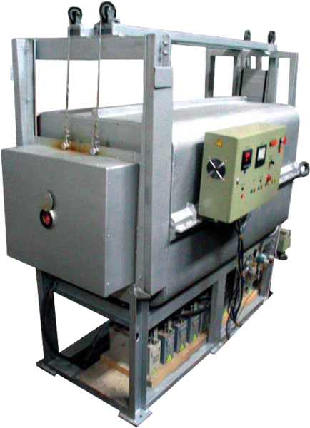
The PIN-1 induction heating furnace is designed to heat ceramic mold blocks before pouring metal.
The product is heated by radiation from a thin-walled muffle heated by the energy of a high-frequency electromagnetic field, the source of which is the inductor. Due to the large radiation surface of the muffle, sufficient power coverage and low heat capacity of the thermal insulation, fast and uniform heating of the product is achieved. This allows loading products into a cold furnace, ensuring the product heating rate required by the technology.
The PIN-1 furnace consists of the following units:
- Induction furnace,
- Control panel with electrical equipment,
- Recording console,
- Electrical wiring,
- Pressure and drain collector,
- Thyristor frequency converter "TPChT-250".
The structure and operation of the PIN-1 furnace and its components.
The PIN-1 furnace structurally consists of an induction furnace, which consists of a heating chamber installed on a frame. The front end of the furnace is closed by a door that moves up and down along the guides with the help of a pneumatic cylinder.
The pneumatic cylinder is located on the upper frame of the furnace. The pneumatic cylinder rod is connected to the door with a cable thrown over two blocks. To prevent spontaneous movement of the door, the latter is balanced by a counterweight.
The guides are made of channels in which the door moves on rollers.
The door is pressed against the chamber using two pneumatic cylinders located on the sides along the chamber. The door is pressed and squeezed using a three-way pneumatic valve installed on the side of the control panel with electrical equipment.
The heating chamber consists of an upper casing, a left casing and a right casing. All casings have a cooling jacket. The casings are fastened to each other with bolts that have electrically insulating bushings.
Three lower brackets made of angle are installed inside the casing. An arc is attached to the brackets, connecting the upper parts of the brackets. Inside the brackets, magnetic circuits are evenly placed to protect the casings from induction heating.
An inductor consisting of two water-cooled electrically insulated coils is placed on the magnetic circuits.
The inner surface of the inductor has thermal insulation. Thermal insulation bricks are placed on the lower part of the inductor, on which the muffle is installed, previously thermally insulated from the outside.
The rear part of the heating chamber is lined with thermal insulation material. The door has thermal insulation. The heating chamber is installed on a frame structure made of channels. In the lower part of the frame, under the chamber, on wooden flooring, condensers are installed. On the side heating chamber, on the side of the control panel with electrical equipment, a pneumatic panel with an air preparation unit is attached. The heating chamber has thermocouples, one located in the rear end part, two on the side. This ensures measurement of the temperature of both the muffle itself and the working space of the chamber.
The control panel with electrical equipment is designed to provide control of heating and temperature measurement, control of water availability and control of door opening and closing.
The recording panel is designed to accommodate a printer that records process parameters.
The electrical wiring is designed to provide power supply from the thyristor frequency converter "TPChT-250" and provide control circuits.
The pressure-drain collector is designed to supply and drain water in the water cooling system that provides cooling of the inductor, heating chamber casings and condensers.
The thyristor frequency converter "TPChT-250" is designed to provide power supply to the furnace heater.
The operation of the unit consists of the following process sequence:
- opening the heating chamber door, loading the charge;
- closing the door;
- turning on the water cooling system;
- turning on the heating, achieving the set furnace temperature;
- removing the charge.
The product is heated by radiation from a thin-walled muffle heated by the energy of a high-frequency electromagnetic field, the source of which is the inductor. Due to the large radiation surface of the muffle, sufficient power coverage and low heat capacity of the thermal insulation, fast and uniform heating of the product is achieved. This allows loading products into a cold furnace, ensuring the product heating rate required by the technology.
The PIN-1 furnace consists of the following units:
- Induction furnace,
- Control panel with electrical equipment,
- Recording console,
- Electrical wiring,
- Pressure and drain collector,
- Thyristor frequency converter "TPChT-250".
The structure and operation of the PIN-1 furnace and its components.
The PIN-1 furnace structurally consists of an induction furnace, which consists of a heating chamber installed on a frame. The front end of the furnace is closed by a door that moves up and down along the guides with the help of a pneumatic cylinder.
The pneumatic cylinder is located on the upper frame of the furnace. The pneumatic cylinder rod is connected to the door with a cable thrown over two blocks. To prevent spontaneous movement of the door, the latter is balanced by a counterweight.
The guides are made of channels in which the door moves on rollers.
The door is pressed against the chamber using two pneumatic cylinders located on the sides along the chamber. The door is pressed and squeezed using a three-way pneumatic valve installed on the side of the control panel with electrical equipment.
The heating chamber consists of an upper casing, a left casing and a right casing. All casings have a cooling jacket. The casings are fastened to each other with bolts that have electrically insulating bushings.
Three lower brackets made of angle are installed inside the casing. An arc is attached to the brackets, connecting the upper parts of the brackets. Inside the brackets, magnetic circuits are evenly placed to protect the casings from induction heating.
An inductor consisting of two water-cooled electrically insulated coils is placed on the magnetic circuits.
The inner surface of the inductor has thermal insulation. Thermal insulation bricks are placed on the lower part of the inductor, on which the muffle is installed, previously thermally insulated from the outside.
The rear part of the heating chamber is lined with thermal insulation material. The door has thermal insulation. The heating chamber is installed on a frame structure made of channels. In the lower part of the frame, under the chamber, on wooden flooring, condensers are installed. On the side heating chamber, on the side of the control panel with electrical equipment, a pneumatic panel with an air preparation unit is attached. The heating chamber has thermocouples, one located in the rear end part, two on the side. This ensures measurement of the temperature of both the muffle itself and the working space of the chamber.
The control panel with electrical equipment is designed to provide control of heating and temperature measurement, control of water availability and control of door opening and closing.
The recording panel is designed to accommodate a printer that records process parameters.
The electrical wiring is designed to provide power supply from the thyristor frequency converter "TPChT-250" and provide control circuits.
The pressure-drain collector is designed to supply and drain water in the water cooling system that provides cooling of the inductor, heating chamber casings and condensers.
The thyristor frequency converter "TPChT-250" is designed to provide power supply to the furnace heater.
The operation of the unit consists of the following process sequence:
- opening the heating chamber door, loading the charge;
- closing the door;
- turning on the water cooling system;
- turning on the heating, achieving the set furnace temperature;
- removing the charge.
Technical data
Supply voltage, V
400
Rated frequency, Hz
50
Phases
3
Installed power, kW
280
Working space dimensions (L*W*H), mm
1550*600*550
Maximal operating temperature, °C
1200
Time for heating the furnace to operating temperature, min
40
Number of control points
3
Working environment
air
Power supply
TPCHT-250
Cooling water consumption, m3/h
9
Cooling water pressure, MPa
0.2-0.25
Overall dimensions (L*W*H), mm
2600*4000*2600
Detailed information PDF
Submit an inquiry
Прошлое
Настоящее
Будущее