
 Personal Account


 Личный Кабинет

Electrothermal compression plant "EKU-N" for soldering

Electrothermal compression plant "EKU-N" for soldering
Description
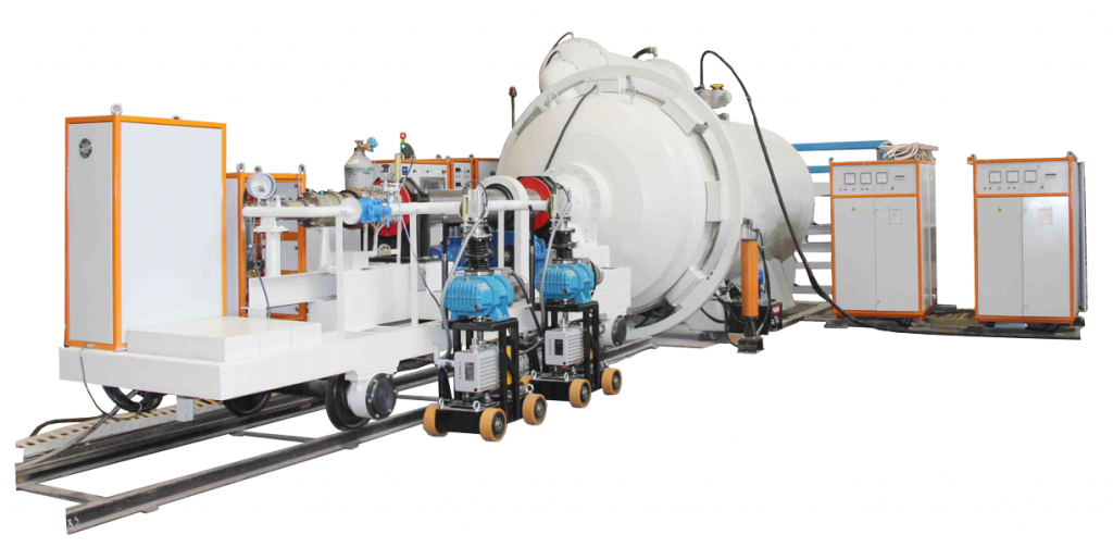
Electrothermal compression unit "EKU-N" for soldering
Purpose of the equipment
Purpose – high-temperature heating for soldering and heat treatment of products with rotation in a neutral gas environment at atmospheric pressure, with vacuuming of the internal cavities of the product.
The "EKU-N" unit is a mechanized muffle induction furnace of increased frequency, equipped with a loading/unloading device, a vacuum system, a power source and equipment for controlling the technological process in automatic mode.
The heating of the assembly unit is carried out by radiation from a thin-walled muffle screen heated by the energy of the electromagnetic field created by the inductor.
The loading of the assembly unit with technological equipment into the working space of the furnace is carried out by the loading/unloading device.
The rotation of the assembly unit with technological equipment is carried out by the spindle of the loading/unloading device from an adjustable frequency electric drive.
The atmosphere is pumped out of the cavity of the assembly unit through the hollow spindle of the loading/unloading device; the waters (leads) of the muffle and assembly unit thermal converters also pass through the spindle.
The compression of the wall and jacket of the assembly unit is achieved by excess pressure of the inert atmosphere created in the furnace body volume.
Forced cooling of the assembly unit under excess pressure of the inert atmosphere is achieved by forced circulation of the atmosphere along a closed circuit: furnace working space - heat exchanger - fan unit - furnace working space.
Design of the "EKU-N" unit
The electrothermal compression unit for soldering and heat treatment of assembly units consists of the following main units and systems:
- Vacuum compression furnace (VCF);
- Loading/unloading device;
- Vacuum system;
- Water cooling system;
- Hydraulic drive station;
- Gas filling system;
- Control cabinet;
- Thyristor frequency converter.
Vacuum compression furnace (VCF)
The furnace consists of a water-cooled casing, an inductor, magnetic cores, a heat exchanger, a fan unit, an elbow, a pipeline, a control and safety device, a collector and a bayonet lock.
The inductor is two-section, water-cooled, the current leads of which go out through the flange openings of the rear casing of the furnace.
The inductor is installed on three lower magnetic cores. Electrical insulation (fiberglass) is laid between the inductor and the magnetic cores.
The purpose of the magnetic cores is to protect the compression casing from the effect of the magnetic field created by the inductor.
The heat exchanger is shell-and-tube, water-cooled. Thermal dampers are installed in the central flanges of the heat exchanger, opening under the pressure of the circulating gas atmosphere along a closed circuit. The purpose of the dampers is to reduce heat loss during natural convection of the gas atmosphere.
The heat exchanger is connected to the furnace body and the fan unit by a water-cooled pipeline and elbow.
The control and safety device is installed on the furnace body. Functions of the control and safety device:
- impossibility of opening the bayonet valve when the excess pressure in the body exceeds 0.003 MPa;
- preventing the supply of compressed gas to the chamber seal when the lid is open.
The manifold is installed on the furnace body and connected to the gas filling cabinet for supplying an inert atmosphere. The following are installed on the manifold: a pressure and vacuum gauge, a valve for emergency pressure relief with a manual drive, a safety valve and a regulating valve for relieving excess pressure in case of deviation from the technical parameters. The manifold is connected by pipelines to the pressure converter and the inflatable seal of the body-lid.
The drain valve (pressure relief) is installed in the upper part of the body. The shut-off valve prevents the penetration of the inert atmosphere into the vacuum system at excess pressure in the working chamber.
The working space of the furnace is thermally insulated with lightweight chamotte.
Loading/unloading device
The loading/unloading device is a self-propelled unit that provides the following operations during the technological process:
- loading/unloading of the assembly unit with technological equipment from the furnace space;
- rotation of the assembly unit with technological equipment relative to the horizontal axis;
- evacuation of the cavity of the assembly unit;
- checking the assembly unit for leaks;
- creation of local excess pressure during heating of the assembly unit.
The supporting structure of the loading/unloading device is a drive frame moving along a rail track by means of electromechanical drives. The drives also provide rotation of the shaft with the assembly unit and the muffle during soldering. Smooth rotation of the CE shaft is provided by a built-in frequency converter.
Vacuum system
The vacuum system is designed to pump out the air in the unit chamber before filling it with neutral gas and to create a vacuum in the CE cavity during soldering. The vacuum system of the unit chamber is located stationary near the chamber body, the vacuum system of the assembly cavity is located on the platform of the loading device or next to it on a rolling trolley.
The vacuum system includes:
- plunger and two-rotor vacuum pumps;
- emergency valve;
- vacuum valve with electromechanical drive Du100;
- emergency bleed valve with electromagnetic drive Du10;
- filter;
- pipelines.
The vacuum system has a connection point for a helium leak detector. An adjustable cooling speed is provided (the rotation speed of the fan motor of the unit by a frequency converter).
Water cooling system The water cooling system is flow-through, connected to the shop system, consists of two manifolds, valves for regulating water flow, a flow relay and pipelines.
Hydraulic drive station
The hydraulic drive station is designed to operate the hydraulic cylinders of the bayonet lock.
The hydraulic drive station is switched on and off from the control panel.
Gas filling system
The gas filling system is designed to fill the cavity of the unit with neutral gas and maintain gas pressure during soldering. The system is adapted to supply gas from cylinders, a cryogenic vessel or a shop network.
The gas filling cabinet provides an inert atmosphere to the body volume, as well as compressed air to the seal and the pneumatic cylinder of the control and safety device, from the shop air pressure system of 20 MPa.
The gas filling cabinet consists of a frame, rear doors, a front panel and front doors.
The following are installed inside the cabinet:
- a step-down reducer;
- safety valves;
- electromagnetic valves;
- a check valve;
- an air release valve.
On the front panel of the cabinet there are pressure measuring devices and handwheels of the shut-off and control equipment.
Control cabinet
The control cabinet ensures:
- carrying out the technological process in an automated mode according to the program;
- the ability to complete the technological process in manual mode in the event of failure of the automatic control system.
The design of the cabinet is similar to the design of the gas filling cabinet and consists of a frame, rear doors, a front panel and front doors. The cabinet is serviced from both sides.
On the front panel of the cabinet there are unit controls, a mnemonic diagram, devices for monitoring electrical parameters, vacuum parameters, as well as an industrial computer.
The frame with electrical equipment contains a PLC controller, relay units, circuit breakers, a buzzer and other electrical equipment, which together constitute the control system of the electrothermal unit.
The control system (CS) of the unit meets the requirements of the technological process for heating rate, holding at certain temperatures, cooling rate, and excess pressure parameters in the unit body and in the assembly unit. CS is based on modern computer technology.
CS organizes the interface with the operator-technologist; serial-parallel control of the vacuum system mechanisms, software control of the heating process, identification of the state of the technological system, documentation of the technological process and dispatching of the above tasks.
Control of the system at the lower level is performed by a certified network controller. Control of the system at the upper level is performed by a personal computer. The controller performs all process control functions, the computer performs only the terminal control task - input, editing and recording of heating and motion programs, visualization of the state of process equipment elements, storage of process history files, diagnostics and errors.
The control system integrates the entire information flow: organization of the interface with the operator and technologist (terminal task); serial-parallel control of the system mechanisms (logical task); software control of the heating process (technological task), regulation of the spindle rotation speed (geometric task), identification of the state of the process system (diagnostic task), documentation of the process (archive task), dispatching of the above tasks (system task).
The upper-level software ensures the implementation of the following functions:
- color graphical interface with the operator, visualization of process parameter values and the state of mechanisms;
- intelligent support of control functions, editing of mnemonic diagrams, rotation and heating programs, archive;
- automatic generation of operational messages based on the analysis of emergency and abnormal situations;
- archive maintenance;
- PLC diagnostics.
The unit is controlled using a touch screen of an industrial computer. When you touch a controlled element, a contextual hint is displayed (what action can be performed), control is possible only in this state and is performed by touching the corresponding key.
The operator interface is implemented based on the following principles:
1. Availability of the main window - “Operational control of the technological process”, which contains a mnemonic diagram of the unit.
2. Archived information about the history of the technological process is stored in the form of tables (Excel format)
3. From the main window, you can call up auxiliary screens, with the help of which the operator specifies changes in the parameters and settings of the control system and performs diagnostics of the system.
4. To view the results and plot a graph of the archiving process, an Excel spreadsheet editor must be installed on the computer.
5. If an error occurs in the operation of the system, a window opens on the personal computer monitor, which displays the error code
A number of solutions are provided for in the development of software:
- operator advisor;
- diagnostics of the reliability of current temperature values.
- formation of an archive file of events, an archive file of technological parameters and an emergency file.
The control system documents the main process parameters of the melt in real time. Documentation is done in a tabular format (Excel) in the PROTOKOL subdirectory in the following files:
- event file
- temperature and vacuum storage file
- error file
and starts automatically after the program is started.
Event file.
The event file header consists of
- program start date
- program start time
- flag indicating the event file – Event
for example, “04/29/21 13:50/22 Event.XLS”
The event file records, with an accuracy of up to a second,
- initial state of mechanisms
- changes in the state of mechanisms
- operations undertaken by the operator
Temperature and vacuum storage file.
The header of the process data save file consists of:
- program start date
- program start time
for example, "04/28/21 10.56.38.XLS"
The process data save file contains the process data passport data, filled in during registration and then once a minute, the values of temperature, vacuum and pressure of the current process
Using this file, you can plot process data graphs using Microsoft Excel
Error file.
The error file header consists of
- program start date
- program start time
- flag indicating the event file – Error
e.g., «04/29/21 13.50.22 Error.XLS»
The following are recorded in the error file with an accuracy of up to a second
- error code
- text description of the error
The control system ensures the operation of the unit in the following modes:
- «Manual control»
- «Automated» (the control cycle includes operations from the moment the unit lid is closed until the moment the housing is depressurized after the end of the technological process)
In the «Manual control» mode, the following is provided:
The industrial-grade personal computer provides the necessary service for operation:
- multi-window ergonomic user interface with color graphics;
- effective system support for all application processes, the use of modern software products developed for the MSWindows operating environment;
- recording a report on the progress of the technological process; the report file can be called up on the monitor for visual analysis and printed in digital and graphic form (protocol) for inclusion in the accompanying documentation.
The protocol of the completed soldering and heat treatment process contains the following information:
- Designation of the soldered CE
- Soldering date
- Ambient temperature
- Soldering temperature
- Current time
- Thermocouple readings
- Shielding gas pressure in the furnace cavity
- Shielding gas pressure in the internal cavity CE
- Vacuum in the soldering cavity CE
- Full name of the operator
The control system has a light signaling system for deviations in the technological process:
- water cooling failure;
- thermocouple breakage;
- other deviations from the normal operation of the unit.
The necessary locks are implemented to ensure safe operation of the unit and service personnel, to prevent incorrect operator actions.
Purpose – high-temperature heating for soldering and heat treatment of products with rotation in a neutral gas environment at atmospheric pressure, with vacuuming of the internal cavities of the product.
The "EKU-N" unit is a mechanized muffle induction furnace of increased frequency, equipped with a loading/unloading device, a vacuum system, a power source and equipment for controlling the technological process in automatic mode.
The heating of the assembly unit is carried out by radiation from a thin-walled muffle screen heated by the energy of the electromagnetic field created by the inductor.
The loading of the assembly unit with technological equipment into the working space of the furnace is carried out by the loading/unloading device.
The rotation of the assembly unit with technological equipment is carried out by the spindle of the loading/unloading device from an adjustable frequency electric drive.
The atmosphere is pumped out of the cavity of the assembly unit through the hollow spindle of the loading/unloading device; the waters (leads) of the muffle and assembly unit thermal converters also pass through the spindle.
The compression of the wall and jacket of the assembly unit is achieved by excess pressure of the inert atmosphere created in the furnace body volume.
Forced cooling of the assembly unit under excess pressure of the inert atmosphere is achieved by forced circulation of the atmosphere along a closed circuit: furnace working space - heat exchanger - fan unit - furnace working space.
Design of the "EKU-N" unit
The electrothermal compression unit for soldering and heat treatment of assembly units consists of the following main units and systems:
- Vacuum compression furnace (VCF);
- Loading/unloading device;
- Vacuum system;
- Water cooling system;
- Hydraulic drive station;
- Gas filling system;
- Control cabinet;
- Thyristor frequency converter.
Vacuum compression furnace (VCF)
The furnace consists of a water-cooled casing, an inductor, magnetic cores, a heat exchanger, a fan unit, an elbow, a pipeline, a control and safety device, a collector and a bayonet lock.
The inductor is two-section, water-cooled, the current leads of which go out through the flange openings of the rear casing of the furnace.
The inductor is installed on three lower magnetic cores. Electrical insulation (fiberglass) is laid between the inductor and the magnetic cores.
The purpose of the magnetic cores is to protect the compression casing from the effect of the magnetic field created by the inductor.
The heat exchanger is shell-and-tube, water-cooled. Thermal dampers are installed in the central flanges of the heat exchanger, opening under the pressure of the circulating gas atmosphere along a closed circuit. The purpose of the dampers is to reduce heat loss during natural convection of the gas atmosphere.
The heat exchanger is connected to the furnace body and the fan unit by a water-cooled pipeline and elbow.
The control and safety device is installed on the furnace body. Functions of the control and safety device:
- impossibility of opening the bayonet valve when the excess pressure in the body exceeds 0.003 MPa;
- preventing the supply of compressed gas to the chamber seal when the lid is open.
The manifold is installed on the furnace body and connected to the gas filling cabinet for supplying an inert atmosphere. The following are installed on the manifold: a pressure and vacuum gauge, a valve for emergency pressure relief with a manual drive, a safety valve and a regulating valve for relieving excess pressure in case of deviation from the technical parameters. The manifold is connected by pipelines to the pressure converter and the inflatable seal of the body-lid.
The drain valve (pressure relief) is installed in the upper part of the body. The shut-off valve prevents the penetration of the inert atmosphere into the vacuum system at excess pressure in the working chamber.
The working space of the furnace is thermally insulated with lightweight chamotte.
Loading/unloading device
The loading/unloading device is a self-propelled unit that provides the following operations during the technological process:
- loading/unloading of the assembly unit with technological equipment from the furnace space;
- rotation of the assembly unit with technological equipment relative to the horizontal axis;
- evacuation of the cavity of the assembly unit;
- checking the assembly unit for leaks;
- creation of local excess pressure during heating of the assembly unit.
The supporting structure of the loading/unloading device is a drive frame moving along a rail track by means of electromechanical drives. The drives also provide rotation of the shaft with the assembly unit and the muffle during soldering. Smooth rotation of the CE shaft is provided by a built-in frequency converter.
Vacuum system
The vacuum system is designed to pump out the air in the unit chamber before filling it with neutral gas and to create a vacuum in the CE cavity during soldering. The vacuum system of the unit chamber is located stationary near the chamber body, the vacuum system of the assembly cavity is located on the platform of the loading device or next to it on a rolling trolley.
The vacuum system includes:
- plunger and two-rotor vacuum pumps;
- emergency valve;
- vacuum valve with electromechanical drive Du100;
- emergency bleed valve with electromagnetic drive Du10;
- filter;
- pipelines.
The vacuum system has a connection point for a helium leak detector. An adjustable cooling speed is provided (the rotation speed of the fan motor of the unit by a frequency converter).
Water cooling system The water cooling system is flow-through, connected to the shop system, consists of two manifolds, valves for regulating water flow, a flow relay and pipelines.
Hydraulic drive station
The hydraulic drive station is designed to operate the hydraulic cylinders of the bayonet lock.
The hydraulic drive station is switched on and off from the control panel.
Gas filling system
The gas filling system is designed to fill the cavity of the unit with neutral gas and maintain gas pressure during soldering. The system is adapted to supply gas from cylinders, a cryogenic vessel or a shop network.
The gas filling cabinet provides an inert atmosphere to the body volume, as well as compressed air to the seal and the pneumatic cylinder of the control and safety device, from the shop air pressure system of 20 MPa.
The gas filling cabinet consists of a frame, rear doors, a front panel and front doors.
The following are installed inside the cabinet:
- a step-down reducer;
- safety valves;
- electromagnetic valves;
- a check valve;
- an air release valve.
On the front panel of the cabinet there are pressure measuring devices and handwheels of the shut-off and control equipment.
Control cabinet
The control cabinet ensures:
- carrying out the technological process in an automated mode according to the program;
- the ability to complete the technological process in manual mode in the event of failure of the automatic control system.
The design of the cabinet is similar to the design of the gas filling cabinet and consists of a frame, rear doors, a front panel and front doors. The cabinet is serviced from both sides.
On the front panel of the cabinet there are unit controls, a mnemonic diagram, devices for monitoring electrical parameters, vacuum parameters, as well as an industrial computer.
The frame with electrical equipment contains a PLC controller, relay units, circuit breakers, a buzzer and other electrical equipment, which together constitute the control system of the electrothermal unit.
The control system (CS) of the unit meets the requirements of the technological process for heating rate, holding at certain temperatures, cooling rate, and excess pressure parameters in the unit body and in the assembly unit. CS is based on modern computer technology.
CS organizes the interface with the operator-technologist; serial-parallel control of the vacuum system mechanisms, software control of the heating process, identification of the state of the technological system, documentation of the technological process and dispatching of the above tasks.
Control of the system at the lower level is performed by a certified network controller. Control of the system at the upper level is performed by a personal computer. The controller performs all process control functions, the computer performs only the terminal control task - input, editing and recording of heating and motion programs, visualization of the state of process equipment elements, storage of process history files, diagnostics and errors.
The control system integrates the entire information flow: organization of the interface with the operator and technologist (terminal task); serial-parallel control of the system mechanisms (logical task); software control of the heating process (technological task), regulation of the spindle rotation speed (geometric task), identification of the state of the process system (diagnostic task), documentation of the process (archive task), dispatching of the above tasks (system task).
The upper-level software ensures the implementation of the following functions:
- color graphical interface with the operator, visualization of process parameter values and the state of mechanisms;
- intelligent support of control functions, editing of mnemonic diagrams, rotation and heating programs, archive;
- automatic generation of operational messages based on the analysis of emergency and abnormal situations;
- archive maintenance;
- PLC diagnostics.
The unit is controlled using a touch screen of an industrial computer. When you touch a controlled element, a contextual hint is displayed (what action can be performed), control is possible only in this state and is performed by touching the corresponding key.
The operator interface is implemented based on the following principles:
1. Availability of the main window - “Operational control of the technological process”, which contains a mnemonic diagram of the unit.
2. Archived information about the history of the technological process is stored in the form of tables (Excel format)
3. From the main window, you can call up auxiliary screens, with the help of which the operator specifies changes in the parameters and settings of the control system and performs diagnostics of the system.
4. To view the results and plot a graph of the archiving process, an Excel spreadsheet editor must be installed on the computer.
5. If an error occurs in the operation of the system, a window opens on the personal computer monitor, which displays the error code
A number of solutions are provided for in the development of software:
- operator advisor;
- diagnostics of the reliability of current temperature values.
- formation of an archive file of events, an archive file of technological parameters and an emergency file.
The control system documents the main process parameters of the melt in real time. Documentation is done in a tabular format (Excel) in the PROTOKOL subdirectory in the following files:
- event file
- temperature and vacuum storage file
- error file
and starts automatically after the program is started.
Event file.
The event file header consists of
- program start date
- program start time
- flag indicating the event file – Event
for example, “04/29/21 13:50/22 Event.XLS”
The event file records, with an accuracy of up to a second,
- initial state of mechanisms
- changes in the state of mechanisms
- operations undertaken by the operator
Temperature and vacuum storage file.
The header of the process data save file consists of:
- program start date
- program start time
for example, "04/28/21 10.56.38.XLS"
The process data save file contains the process data passport data, filled in during registration and then once a minute, the values of temperature, vacuum and pressure of the current process
Using this file, you can plot process data graphs using Microsoft Excel
Error file.
The error file header consists of
- program start date
- program start time
- flag indicating the event file – Error
e.g., «04/29/21 13.50.22 Error.XLS»
The following are recorded in the error file with an accuracy of up to a second
- error code
- text description of the error
The control system ensures the operation of the unit in the following modes:
- «Manual control»
- «Automated» (the control cycle includes operations from the moment the unit lid is closed until the moment the housing is depressurized after the end of the technological process)
In the «Manual control» mode, the following is provided:
The industrial-grade personal computer provides the necessary service for operation:
- multi-window ergonomic user interface with color graphics;
- effective system support for all application processes, the use of modern software products developed for the MSWindows operating environment;
- recording a report on the progress of the technological process; the report file can be called up on the monitor for visual analysis and printed in digital and graphic form (protocol) for inclusion in the accompanying documentation.
The protocol of the completed soldering and heat treatment process contains the following information:
- Designation of the soldered CE
- Soldering date
- Ambient temperature
- Soldering temperature
- Current time
- Thermocouple readings
- Shielding gas pressure in the furnace cavity
- Shielding gas pressure in the internal cavity CE
- Vacuum in the soldering cavity CE
- Full name of the operator
The control system has a light signaling system for deviations in the technological process:
- water cooling failure;
- thermocouple breakage;
- other deviations from the normal operation of the unit.
The necessary locks are implemented to ensure safe operation of the unit and service personnel, to prevent incorrect operator actions.
Technical data
Maximal operating temperature, °C
1250
Heating time of the part to 1200 °C
90
Cooling time of the part from 1200 °C to 600 °C, min.
25
Temperature-measured points on the part
3
Overall dimensions of the part (Ø*D), mm
(500-1200)*(700-2000)
Residual pressure in the part cavity, Pa
≤1
Maximal excess pressure in the working volume of the compression housing, MPa
1,2
Spindle rotation speed of the loading and unloading device, min-1
4-5
Process mode
auto
Maximal permissible bending moment on the spindle console of the loading and unloading device, kgf m
7000
Maximal consumption of inert atmosphere for one technological process, gas balloon (P=15MPa, V=40l), pcs.
32
Inductor power, kW
700
Inductor supply frequency, Hz
2400
Inductor supply voltage, V
0-800
Installed power, kW
950
Water consumption for cooling at inlet temperature 20ºС, m3/hour
20
Occupied area, m2
172
Weight, kg
26000
Submit an inquiry
Прошлое
Настоящее
Будущее