
 Personal Account


 Личный Кабинет

Plasma deposition complex "UPU-12K.1"

Plasma deposition complex "UPU-12K.1"
Description
Plasma deposition complex "UPU-12K.1" of powder materials of boron or gadolinium oxide in the working chamber.
 Detailed information PDF
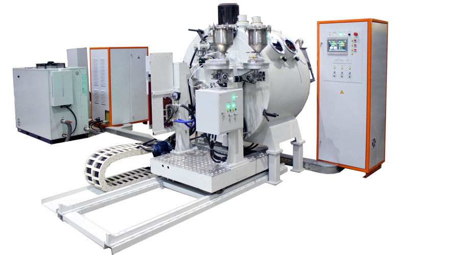
The UPU-12K.1 plasma spraying complex is designed for spraying powder materials from boron or gadolinium oxide using the plasma spraying method in the working chamber.
The UPU-12K.1 complex consists of:
- Chamber,
- Sliding door,
- Machine complex,
- Powder collection tray,
- Powder feed system,
- Gas system,
- Water cooling system,
- Current supply,
- Electrical wiring,
- Rail track,
- Rotator,
- Metal structure,
- Control cabinet,
- Plasmatron P2,
- Power cabinet,
- Plasma spraying rectifier VPN-650-01,
- Powder dispenser drive cabinet.
The structure and operation of the complex and its components
The UPU-12K.1 complex is a chamber installation consisting of the following components: mechanical, power, automated control system, cooling system
The coating application on the UPU-12K.1 complex is carried out by a plasma jet by depositing particles of the sprayed material on the product, introduced into the plasma jet in the form of powder. When colliding with the product, the particles, which are in a molten or plastic state, are deformed and embedded in the microroughness of the product or plastically deform it with the formation of common points of physical and chemical interaction, ensuring the strength of adhesion and density of the coating. The formation of a coating layer of the required thickness is carried out by layer-by-layer spraying, when the plasma torch moves relative to the sprayed surface.
The chamber contains:
- sprayed products strung on mandrels (six mandrels in total), the mandrels are mounted on a movable plate;
- plasma torch movement mechanism;
- powder collection tray.
The powders to be applied are fed into the plasma torch from dispensers by a flow of transport gas (argon) through elastic tubes.
The process is monitored through the viewing windows of the chamber. For ease of maintenance of the unit and installation of sprayed products, a sliding door with an electromechanical drive is provided.
The machine complex includes a mechanism that ensures fastening, positioning and movement of the plasma torch (longitudinal - axis "X", vertical - axis "Z", as well as its adjustment rotation - axis "XY") during the technological process of plasma spraying, fulfilling the conditions for applying powder along the axis of the workpiece. The moving elements of the machine complex are hidden under a protective casing.
The gas system consists of flexible pipeline lines with shut-off and control valves that allow the technological process of powder spraying onto workpieces to be carried out. Plasma-forming gases – argon, helium. Transporting – argon.
The water cooling system is closed. The coolant is distilled or softened water. The system is designed to supply and drain water required to cool the elements of the unit structure during the technological process.
The electrical wiring is designed to supply power to electric motors, drive devices, as well as to supply control circuits from units and a control cabinet and consists of a busbar, harnesses with electric drives, protective covers and boxes.
The control cabinet is located next to the operator's workplace, on the front panel of which an LCD panel with virtual control buttons is installed.
The rectifier "VPN-650-01" is a power source for the plasma torch and is located separately next to the unit.
The power cabinet is used to connect power supply lines to the unit.
The powder dispenser drive cabinet is located on the right pillar of the sliding door. The control buttons for the dispenser drives are located on the front panel of the cabinet.
The plasma torch is located inside the chamber and is used to spray powder materials onto the workpiece using the plasma spraying method. The plasma torch rod cathode is secured using a collet and a nut screwed into the cathode holder. To generate a plasma jet in the plasma torch, a plasma-forming gas is supplied to the arc chamber, and voltage from the power source is supplied to the water-cooled cathode and anode parts. After the arc gap between the cathode (electrode) and the anode (nozzle) is broken down, an arc is excited by the spark discharge of the oscillator, which ionizes the gas passing through the arc chamber of the nozzle, turning it into a plasma jet. The coating material in the form of powder is introduced into the plasma jet, where it is heated and the particles of the sprayed material are accelerated.
The UPU-12K.1 complex consists of:
- Chamber,
- Sliding door,
- Machine complex,
- Powder collection tray,
- Powder feed system,
- Gas system,
- Water cooling system,
- Current supply,
- Electrical wiring,
- Rail track,
- Rotator,
- Metal structure,
- Control cabinet,
- Plasmatron P2,
- Power cabinet,
- Plasma spraying rectifier VPN-650-01,
- Powder dispenser drive cabinet.
The structure and operation of the complex and its components
The UPU-12K.1 complex is a chamber installation consisting of the following components: mechanical, power, automated control system, cooling system
The coating application on the UPU-12K.1 complex is carried out by a plasma jet by depositing particles of the sprayed material on the product, introduced into the plasma jet in the form of powder. When colliding with the product, the particles, which are in a molten or plastic state, are deformed and embedded in the microroughness of the product or plastically deform it with the formation of common points of physical and chemical interaction, ensuring the strength of adhesion and density of the coating. The formation of a coating layer of the required thickness is carried out by layer-by-layer spraying, when the plasma torch moves relative to the sprayed surface.
The chamber contains:
- sprayed products strung on mandrels (six mandrels in total), the mandrels are mounted on a movable plate;
- plasma torch movement mechanism;
- powder collection tray.
The powders to be applied are fed into the plasma torch from dispensers by a flow of transport gas (argon) through elastic tubes.
The process is monitored through the viewing windows of the chamber. For ease of maintenance of the unit and installation of sprayed products, a sliding door with an electromechanical drive is provided.
The machine complex includes a mechanism that ensures fastening, positioning and movement of the plasma torch (longitudinal - axis "X", vertical - axis "Z", as well as its adjustment rotation - axis "XY") during the technological process of plasma spraying, fulfilling the conditions for applying powder along the axis of the workpiece. The moving elements of the machine complex are hidden under a protective casing.
The gas system consists of flexible pipeline lines with shut-off and control valves that allow the technological process of powder spraying onto workpieces to be carried out. Plasma-forming gases – argon, helium. Transporting – argon.
The water cooling system is closed. The coolant is distilled or softened water. The system is designed to supply and drain water required to cool the elements of the unit structure during the technological process.
The electrical wiring is designed to supply power to electric motors, drive devices, as well as to supply control circuits from units and a control cabinet and consists of a busbar, harnesses with electric drives, protective covers and boxes.
The control cabinet is located next to the operator's workplace, on the front panel of which an LCD panel with virtual control buttons is installed.
The rectifier "VPN-650-01" is a power source for the plasma torch and is located separately next to the unit.
The power cabinet is used to connect power supply lines to the unit.
The powder dispenser drive cabinet is located on the right pillar of the sliding door. The control buttons for the dispenser drives are located on the front panel of the cabinet.
The plasma torch is located inside the chamber and is used to spray powder materials onto the workpiece using the plasma spraying method. The plasma torch rod cathode is secured using a collet and a nut screwed into the cathode holder. To generate a plasma jet in the plasma torch, a plasma-forming gas is supplied to the arc chamber, and voltage from the power source is supplied to the water-cooled cathode and anode parts. After the arc gap between the cathode (electrode) and the anode (nozzle) is broken down, an arc is excited by the spark discharge of the oscillator, which ionizes the gas passing through the arc chamber of the nozzle, turning it into a plasma jet. The coating material in the form of powder is introduced into the plasma jet, where it is heated and the particles of the sprayed material are accelerated.
Technical data
Sprayed material
boron powder, gadolinium oxide
Installed power, kW
120
Number of dispensers, pcs.
2
Maximal capacity of the dispenser, m3
0.0045
Maximal powder feed capacity of the dispenser, kg/hour
1.2
Maximal power of the plasma torch, kW
25
Range of operating voltage on the plasma torch, V
25 - 70
Plasma-forming gases
argon, helium
Transport gas
argon
Gas flow rate, l/min
5 - 100
Longitudinal movement of the plasma torch manipulator (along the X axis), mm
400
Vertical movement of the plasma torch manipulator (along the Z axis), mm
200
Tuning rotation of the plasma torch manipulator (around the Y axis), deg
90
Overall dimensions (L*W*H), mm
4000*2400*2300
Weight, kg
4000
Detailed information PDF
Submit an inquiry
Прошлое
Настоящее
Будущее