
 Personal Account


 Личный Кабинет

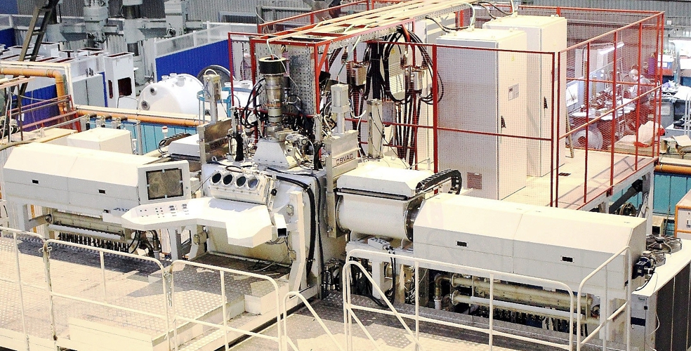
Vacuum electron-beam coating plant "UEN-500"

Vacuum electron-beam coating plant "UEN-500"
Description
Vacuum electron beam plant "UEN-500" for deposition of single-layer and multi-layer coatings in a vacuum.
 Detailed information PDF
1. Purpose of the equipment. Technological processes used in the equipment.
The UPU-10S unit is designed to apply metallic materials to the surfaces of products using the plasma spraying method of wear-resistant, corrosion-resistant, heat-protective, sealing and other special coatings.
2. Features of the physical processes used.
The operation of the UPU-10S plasma spraying unit consists of applying coatings using a plasma jet by depositing particles of the sprayed material on the product, introduced into the plasma jet in the form of powder.
When colliding with the product, the particles, which are in a molten or plastic state, are deformed and embedded in the microroughness of the product or plastically deform it with the formation of common points of physical and chemical interaction, ensuring the adhesion strength and density of the coating. The formation of a coating layer of the required thickness is carried out by layer-by-layer spraying while moving the plasma torch relative to the sprayed surface.
3. The design of the unit.
The UPU-10S unit is designed as a capsule with noise-absorbing walls. The capsule is equipped with a mechanical door for loading parts. There are inspection windows on the capsule door and on the side wall.
Inside the capsule there is a positioning mechanism consisting of a plasma torch positioning mechanism, a rotator (positioner) and a three-jaw lathe chuck.
Description of the unit units.
The UPU-10S unit includes the following main units:
- Positioning mechanism;
- Rotator (positioner);
- Blow-off system;
- Water cooling system;
- Dispenser;
- Platform;
- Plasma torch;
- Frame;
- Gas cabinet;
- Control cabinet;
- Electrical wiring;
- VPN-650 plasma spraying rectifier.
Plasma torch positioning mechanism.
The plasma torch positioning mechanism allows smooth movement of the plasma torch along the X (horizontal movement) and Y (vertical movement) axes according to the control program.
Rotator (positioner).
The rotator (positioner) is equipped with a self-centering lathe chuck, allowing the sprayed part with a diameter of 4 - 500 mm to be fixed. Rotation is performed by a mechanical drive with the ability to regulate the rotation speed within 1 - 16 rpm.
Purge system.
A purge system is connected to the capsule, providing for the removal of process gases and the collection of particles of sprayed powders during the spraying process. The system consists of an inertial cyclone, a radial fan and pipes. The radial fan has an outlet for connection to the exhaust ventilation.
Water cooling system.
The water cooling system is designed to supply and drain water required to cool the cathode and current leads of the plasma torch, the plasma spray rectifier and the cyclone included in the purging system.
The system is single-circuit closed based on a chiller, with a booster pump installed on the coolant supply line to the plasma torch.
The water flow through the channels is monitored by liquid flow sensors installed on the drain.
Dispensers.
There are two dispensers on the roof of the capsule. The dispenser consists of a hopper, an electromechanical drive, and a tilt mechanism.
Uniform powder pouring is achieved by using a cascade of cones and changing the diameter of the nozzle of the replaceable cone.
Powder consumption is determined by the rotation frequency of the electric motor, the amplitude of the oscillation of the tray, changing the position of the dispenser using the tilt mechanism, and changing the diameter and size of the gap to the hopper.
Powder pouring from the tray into the receiving hopper is based on the principle of moving bulk materials along a horizontal vibrating tray.
From the receiving hopper, the powder is fed by the transport gas to the plasma torch.
The data on the flow rate of the transport gas are determined by the gas flow sensor and are displayed on the operator panel of the control system. The flow rate of the sprayed powder is measured according to the calibration data depending on the rotation speed of the vibrator motor of the dispenser and is also displayed on the operator panel of the control system.
Site.
The platform allows servicing the dispensers installed on the roof of the capsule. The collector and booster pump of the water cooling system are also attached to the platform.
Plasma torch for spraying powder materials.
The plasma torch for spraying powder materials is a dismountable structure consisting of a cathode and anode parts separated by an insulator. The plasma jet is generated in the plasma torch as follows. Plasma-forming gas is supplied to the arc chamber, and voltage from the power source is supplied to the water-cooled cathode and anode parts. After the arc gap between the cathode (electrode) and the anode (nozzle) is broken down, an arc is excited, which ionizes the gas passing through the arc chamber of the nozzle, turning it into a plasma jet.
Ramp.
The ramp is used to install two gas cylinders equipped with reducers for adjusting and safely supplying gases to the gas cabinet.
Gas cabinet and control cabinet.
The gas cabinet and control cabinet are designed to ensure uninterrupted operation and control of the technological process performed on the unit.
Electrical wiring.
The electrical wiring is designed to supply power to the plasma spraying rectifier, drives, rotator electric motor, sensors, and valves. It consists of a busbar, harnesses with electric wires, the necessary protective covers and boxes.
Plasma spraying rectifier "VPN-650".
The plasma spraying rectifier "VPN-650" is made according to the thyristor rectifier circuit and is designed to power plasma spraying units.
Control system.
The automated control system of the plasma spraying unit "UPU-10S" with a plasma torch positioning device includes the following components: control cabinet, gas cabinet, plasma spraying rectifier "VPN-650".
The control system of the UPU-10S installation ensures automatic entry of the complex into the spraying mode and completion of the process, with registration and documentation of the process parameters.
The UPU-10S unit is designed to apply metallic materials to the surfaces of products using the plasma spraying method of wear-resistant, corrosion-resistant, heat-protective, sealing and other special coatings.
2. Features of the physical processes used.
The operation of the UPU-10S plasma spraying unit consists of applying coatings using a plasma jet by depositing particles of the sprayed material on the product, introduced into the plasma jet in the form of powder.
When colliding with the product, the particles, which are in a molten or plastic state, are deformed and embedded in the microroughness of the product or plastically deform it with the formation of common points of physical and chemical interaction, ensuring the adhesion strength and density of the coating. The formation of a coating layer of the required thickness is carried out by layer-by-layer spraying while moving the plasma torch relative to the sprayed surface.
3. The design of the unit.
The UPU-10S unit is designed as a capsule with noise-absorbing walls. The capsule is equipped with a mechanical door for loading parts. There are inspection windows on the capsule door and on the side wall.
Inside the capsule there is a positioning mechanism consisting of a plasma torch positioning mechanism, a rotator (positioner) and a three-jaw lathe chuck.
Description of the unit units.
The UPU-10S unit includes the following main units:
- Positioning mechanism;
- Rotator (positioner);
- Blow-off system;
- Water cooling system;
- Dispenser;
- Platform;
- Plasma torch;
- Frame;
- Gas cabinet;
- Control cabinet;
- Electrical wiring;
- VPN-650 plasma spraying rectifier.
Plasma torch positioning mechanism.
The plasma torch positioning mechanism allows smooth movement of the plasma torch along the X (horizontal movement) and Y (vertical movement) axes according to the control program.
Rotator (positioner).
The rotator (positioner) is equipped with a self-centering lathe chuck, allowing the sprayed part with a diameter of 4 - 500 mm to be fixed. Rotation is performed by a mechanical drive with the ability to regulate the rotation speed within 1 - 16 rpm.
Purge system.
A purge system is connected to the capsule, providing for the removal of process gases and the collection of particles of sprayed powders during the spraying process. The system consists of an inertial cyclone, a radial fan and pipes. The radial fan has an outlet for connection to the exhaust ventilation.
Water cooling system.
The water cooling system is designed to supply and drain water required to cool the cathode and current leads of the plasma torch, the plasma spray rectifier and the cyclone included in the purging system.
The system is single-circuit closed based on a chiller, with a booster pump installed on the coolant supply line to the plasma torch.
The water flow through the channels is monitored by liquid flow sensors installed on the drain.
Dispensers.
There are two dispensers on the roof of the capsule. The dispenser consists of a hopper, an electromechanical drive, and a tilt mechanism.
Uniform powder pouring is achieved by using a cascade of cones and changing the diameter of the nozzle of the replaceable cone.
Powder consumption is determined by the rotation frequency of the electric motor, the amplitude of the oscillation of the tray, changing the position of the dispenser using the tilt mechanism, and changing the diameter and size of the gap to the hopper.
Powder pouring from the tray into the receiving hopper is based on the principle of moving bulk materials along a horizontal vibrating tray.
From the receiving hopper, the powder is fed by the transport gas to the plasma torch.
The data on the flow rate of the transport gas are determined by the gas flow sensor and are displayed on the operator panel of the control system. The flow rate of the sprayed powder is measured according to the calibration data depending on the rotation speed of the vibrator motor of the dispenser and is also displayed on the operator panel of the control system.
Site.
The platform allows servicing the dispensers installed on the roof of the capsule. The collector and booster pump of the water cooling system are also attached to the platform.
Plasma torch for spraying powder materials.
The plasma torch for spraying powder materials is a dismountable structure consisting of a cathode and anode parts separated by an insulator. The plasma jet is generated in the plasma torch as follows. Plasma-forming gas is supplied to the arc chamber, and voltage from the power source is supplied to the water-cooled cathode and anode parts. After the arc gap between the cathode (electrode) and the anode (nozzle) is broken down, an arc is excited, which ionizes the gas passing through the arc chamber of the nozzle, turning it into a plasma jet.
Ramp.
The ramp is used to install two gas cylinders equipped with reducers for adjusting and safely supplying gases to the gas cabinet.
Gas cabinet and control cabinet.
The gas cabinet and control cabinet are designed to ensure uninterrupted operation and control of the technological process performed on the unit.
Electrical wiring.
The electrical wiring is designed to supply power to the plasma spraying rectifier, drives, rotator electric motor, sensors, and valves. It consists of a busbar, harnesses with electric wires, the necessary protective covers and boxes.
Plasma spraying rectifier "VPN-650".
The plasma spraying rectifier "VPN-650" is made according to the thyristor rectifier circuit and is designed to power plasma spraying units.
Control system.
The automated control system of the plasma spraying unit "UPU-10S" with a plasma torch positioning device includes the following components: control cabinet, gas cabinet, plasma spraying rectifier "VPN-650".
The control system of the UPU-10S installation ensures automatic entry of the complex into the spraying mode and completion of the process, with registration and documentation of the process parameters.
Technical data
Dimensions of a cylindrical cassette with products (Ø*D), mm
380*500
Rotation speed of the product on a horizontal rod, rpm
1 - 50
Crucibles, pcs.
3
Inner diameter of crucibles, mm
70
Length of evaporated ingots, mm
500
Ingot feeding speed, mm/min
0.3 - 30
Electron guns for evaporating materials from crucibles, pcs.
3
Electron guns for heating products, pcs.
1
Rated power of the electron gun, kW
150
Rated operating accelerating voltage, kV
30
Operating vacuum in the coating chamber, Pa (mm Hg)
1*10-3 - 6*10-3 (1*10-5 – 5*10-5)
Airlock chamber evacuation time, min
2 - 3
Sluice gate opening time, s
8 - 10
Rated voltage of the three-phase alternating current supply network with a frequency of 50 Hz, V
400±10%
Cooling water pressure, Pa (kgf/cm2)
3*105 – 4*105 (3 - 4)
Installed power, kW
1100
Overall dimensions (L*W*H), mm 1
0900*9030*4500
Weight, kg
25000
Detailed information PDF
Submit an inquiry
Прошлое
Настоящее
Будущее