
 Personal Account


 Личный Кабинет

Plant "UMP-500" for deposition of coating

Plant "UMP-500" for deposition of coating
Description
Plant "UMP-500" for deposition of multi-component coatings via gas circulation method
 Detailed information PDF

"UMP-500" plant is designed for deposition of protective coatings via gas circulation method.
This method of deposition is used to protect the surface of steel with chromium. Passing vaporous chromium chloride over the surface of steel heated to 1000°C ensures the formation of a chromium coating firmly adhered to the base through an intermediate layer of Fe-Cr alloy with a chromium content of up to 30%. The advantages of the method are the low porosity of the coatings and the possibility of metallization of internal surfaces and parts of complex configurations; the disadvantage is low productivity due to diffusion processes or chemical reactions at the interface.
With the vacuum method, chromed products are either in contact with chromium powder or at some distance from it. The vacuum facilitates the evaporation of chromium and its transfer to the surface being treated. The saturation of the surface with chromium occurs due to the formation of a vapor phase containing chromium at high temperature.
"UMP-500" is a modern equipment and is characterized by a compact design, equipped with a coating reactor.

Design of "UMP-500".
The plant consists of main parts:
1. Vacuum chamber;
2. Intra-chamber section of the electric furnace;
3. Screen-heater (muffle);
4. Lifting mechanism;
5. Base;
6. Vacuum system;
7. Control cabinet;
8. Power cabinet;
9. Transformer cabinet;
10. Water cooling system.
Operating principle of the "UMP-500" unit.
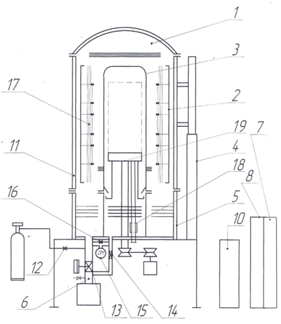
A fan, evaporator, vacuum system connection pipes, and a support for the heating screen (muffle) are mounted on the base 5, which is the lower part of the vacuum chamber 1. The heating screen (muffle) 3 is a welded thin-walled cylinder made of chemically resistant sheet material. The lifting mechanism 4 is used to install and remove the vacuum chamber from the base 1. Inside the vacuum chamber, there is an electric furnace section 2 equipped with screen thermal insulation and a three-phase resistance heater fed by a transformer cabinet 10. The furnace is heated after evacuation of the furnace and the intra-muffle space by a vacuum system 6 through valves 3 and 4. The pressure equalization valve 16 is open. In addition to measuring the pressures in the cavity of the heating screen (muffle) and outside it, the difference in these pressures is measured by a differential pressure gauge 15, the signal from which acts on the control system 7, which forms an effect on the valves of the vacuum system to maintain equal pressures inside and outside the muffle. When the furnace is heated and the evaporator is put into operation, the equalizing valve 16 closes, the vacuum system is switched off by valves 13, 14.
During evaporation, the pressure in the intra-muffle working space increases. The control system, by acting on the inert gas leak 12 and, if necessary, on the bypass of valve 13, maintains the equality of the volume pressures, eliminating the mechanical load on the muffle walls. Elimination of mechanical loads on the muffle from the pressure difference at the operating temperature significantly increases its service life. In addition, the small thermal mass of the thin-walled muffle allows more efficient maintenance of the temperature in the working space by a multi-zone heater. The transformer cabinet, vacuum chamber and base are cooled by a water cooling system 11, using water from the workshop network of circulating technical water supply. The electrical systems of the installation are equipped with modern starting and regulating and automatic protective equipment mounted in the power cabinet 8.
A circulation fan 19 and an evaporator 18, as well as the connection pipes of the vacuum system, are installed on the bottom of the vacuum chamber base. The equipment with the charge is installed on special supports above the fan. The internal space of the heating screen (muffle) is a reactor in which, when heated due to the evaporation of chemical reagents, a specified pressure of the working gas medium is created. This pressure is controlled by a differential pressure sensor, with the help of which a proportional pressure outside the muffle is maintained by injecting inert gas. The gas flow is circulated by a fan. During the technological cycle, it is possible to change the gas flow by acting on the frequency drive of the fan electric motor.
Registration of the technological process parameters of the charge occurs automatically and forms the necessary archive files on the hard disk of the control computer, which make up the charge passport.
The vacuum system consists of a mechanical forevacuum pump and a Roots pump, valves, pipelines and the necessary vacuum and pressure sensors.
This method of deposition is used to protect the surface of steel with chromium. Passing vaporous chromium chloride over the surface of steel heated to 1000°C ensures the formation of a chromium coating firmly adhered to the base through an intermediate layer of Fe-Cr alloy with a chromium content of up to 30%. The advantages of the method are the low porosity of the coatings and the possibility of metallization of internal surfaces and parts of complex configurations; the disadvantage is low productivity due to diffusion processes or chemical reactions at the interface.
With the vacuum method, chromed products are either in contact with chromium powder or at some distance from it. The vacuum facilitates the evaporation of chromium and its transfer to the surface being treated. The saturation of the surface with chromium occurs due to the formation of a vapor phase containing chromium at high temperature.
"UMP-500" is a modern equipment and is characterized by a compact design, equipped with a coating reactor.
Design of "UMP-500".
The plant consists of main parts:
1. Vacuum chamber;
2. Intra-chamber section of the electric furnace;
3. Screen-heater (muffle);
4. Lifting mechanism;
5. Base;
6. Vacuum system;
7. Control cabinet;
8. Power cabinet;
9. Transformer cabinet;
10. Water cooling system.
Operating principle of the "UMP-500" unit.
A fan, evaporator, vacuum system connection pipes, and a support for the heating screen (muffle) are mounted on the base 5, which is the lower part of the vacuum chamber 1. The heating screen (muffle) 3 is a welded thin-walled cylinder made of chemically resistant sheet material. The lifting mechanism 4 is used to install and remove the vacuum chamber from the base 1. Inside the vacuum chamber, there is an electric furnace section 2 equipped with screen thermal insulation and a three-phase resistance heater fed by a transformer cabinet 10. The furnace is heated after evacuation of the furnace and the intra-muffle space by a vacuum system 6 through valves 3 and 4. The pressure equalization valve 16 is open. In addition to measuring the pressures in the cavity of the heating screen (muffle) and outside it, the difference in these pressures is measured by a differential pressure gauge 15, the signal from which acts on the control system 7, which forms an effect on the valves of the vacuum system to maintain equal pressures inside and outside the muffle. When the furnace is heated and the evaporator is put into operation, the equalizing valve 16 closes, the vacuum system is switched off by valves 13, 14.
During evaporation, the pressure in the intra-muffle working space increases. The control system, by acting on the inert gas leak 12 and, if necessary, on the bypass of valve 13, maintains the equality of the volume pressures, eliminating the mechanical load on the muffle walls. Elimination of mechanical loads on the muffle from the pressure difference at the operating temperature significantly increases its service life. In addition, the small thermal mass of the thin-walled muffle allows more efficient maintenance of the temperature in the working space by a multi-zone heater. The transformer cabinet, vacuum chamber and base are cooled by a water cooling system 11, using water from the workshop network of circulating technical water supply. The electrical systems of the installation are equipped with modern starting and regulating and automatic protective equipment mounted in the power cabinet 8.
A circulation fan 19 and an evaporator 18, as well as the connection pipes of the vacuum system, are installed on the bottom of the vacuum chamber base. The equipment with the charge is installed on special supports above the fan. The internal space of the heating screen (muffle) is a reactor in which, when heated due to the evaporation of chemical reagents, a specified pressure of the working gas medium is created. This pressure is controlled by a differential pressure sensor, with the help of which a proportional pressure outside the muffle is maintained by injecting inert gas. The gas flow is circulated by a fan. During the technological cycle, it is possible to change the gas flow by acting on the frequency drive of the fan electric motor.
Registration of the technological process parameters of the charge occurs automatically and forms the necessary archive files on the hard disk of the control computer, which make up the charge passport.
The vacuum system consists of a mechanical forevacuum pump and a Roots pump, valves, pipelines and the necessary vacuum and pressure sensors.
Technical data
Maximal operating temperature, °C
1000
Uniformity of temperature distribution in the working space, °C
±10
Evaporator temperature, °C
190-220
Carrier gas pressure (argon + chlorides of saturating elements), bar abs.
1.2
Operatinging vacuum up to temperature 600, °C (empty and clean furnace), Pa
6.65
Maximal leakage with an empty, clean muffle, µm Hg × l/s
< 3
Maximal leakage with chloride residues, µm Hg × l/s
< 30
Reactor capacity, l
240
Muffle and cap material alloy
KhN78T (EI 435)
Chamber heating elements alloy
X20N80-N
Heating power, kW
40
Heating zones
3
Weight of cage with equipment, kg
200
Working space dimensions (Ø*H), mm
400*700
Detailed information PDF
Submit an inquiry
Прошлое
Настоящее
Будущее