
 Personal Account


 Личный Кабинет

Vacuum furnace “PV-900/1700”

Vacuum furnace “PV-900/1700”
Description
Vacuum furnace “PV-900/1700” for heat treatment of detales made of titanium alloys
 Detailed information PDF
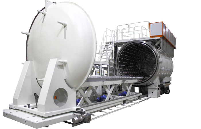
The vacuum furnace “PV-900/1700” is intended for heat treatment of detales made of titanium alloys.
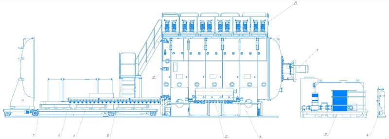
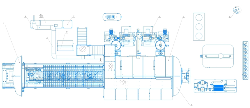
The vacuum furnace “PV-900/1700” consists of the main blocks and units:
1. Chamber,
2. Rear cover,
3. Front cover,
4. Base,
5. Installation table,
6. Trolley,
7. Mechanism for moving the cage,
8. Rail track,
9. Fan drive,
10. Service platform,
11. Vacuum system,
12. Pneumatic system,
13. Water cooling system,
14. Argon inlet system,
15. Electrical wiring,
16. Heating control cabinet,
17. Power cabinet,
18. Control cabinet,
19. Control panel,
20. Transformer block.
1. Chamber.
The heating chamber is cylindrical and made of stainless steel sheets. Flanges are welded to the ends of the cylinder for fastening the rear cover on one side and the front cover on the other.
The chamber has a water cooling jacket divided into 14 zones.
Pipes are welded into the chamber for fastening thermocouples, water-cooled racks, and current leads.
2. Rear cover.
The rear cover is made of two rolled bottoms welded onto a flange. The bottoms are made of stainless steel. The cover has screen thermal insulation.
3. Front cover.
The front cover, like the rear cover, is made of two rolled bottoms, with a cooling jacket formed between the bottoms. The screen thermal insulation is installed on a removable screen.
The front cover is mounted on a trolley and has an adjustment device for normal sealing against the chamber flange.
There are silicone vacuum seals on the front and rear covers.
4. Base.
The base is installed on the rail track.
5. Installation table.
The base for the heat-treated product - the installation table - is installed on the rail track.
6. Trolley.
The trolley is rolled into the heating chamber along the rail track.
7. Load movement mechanism.
The load movement mechanism is designed to load and unload the product from the heating chamber. It is a welded structure that has 4 wheel pairs and a drive with an electric motor for moving it along the rail track.
8. Rail track.
On the side of the front cover, along the longitudinal axis of the heating chamber at the level of the workshop floor, there is a rail track along which the load movement mechanism moves.
9. Fan drive.
A fan for cooling the load in an inert gas environment is installed in the center of the rear cover. Argon is supplied to the chamber using an argon inlet system.
10. Service platform.
The platform is designed for servicing the water cooling system and transformer units.
The water cooling system manifolds and the air preparation unit of the pneumatic system are located on the heating chamber supports, as well as on the platform.
11. Vacuum system.
The vacuum system is designed to create a vacuum in the chamber. Forevacuum pumping is created by 2 pumps. The system has pneumatic valves. The valves installed on the mechanical pumps close automatically when switched off, which prevents oil from being released from the pumps into the pipelines.
12. Pneumatic system.
The pneumatic system is designed to control the pneumatic drives of the vacuum valves and pneumatic clamps. The pneumatic system includes a compressor, an air preparation unit, pneumatic distributors and pipelines.
13. Water cooling system.
The water cooling system is designed to supply and drain water required to cool the furnace and vacuum pumps during the heat treatment mode. The water cooling system is divided into two circuits. The first circuit, which cools the vacuum system, transformers and current leads, includes a chiller, and the second circuit is designed to cool the chamber and the jackets of the front and rear covers.
If there is no water on the drain, an alarm signal is issued.
14. Argon inlet system.
Argon is supplied to the chamber using the argon inlet system.
15. Electrical wiring.
Electrical wiring is designed to provide power supply from transformers to the current leads of the heating chamber and consists of busbars, harnesses with electrical wires, the necessary protective covers and boxes.
16. Heating control cabinet.
The power cabinet, control cabinet, control panel, heating control cabinet are designed to ensure uninterrupted operation and control of the technological process performed in the furnace.
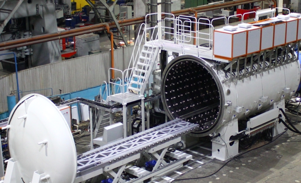
The vacuum furnace “PV-900/1700” consists of the main blocks and units:
1. Chamber,
2. Rear cover,
3. Front cover,
4. Base,
5. Installation table,
6. Trolley,
7. Mechanism for moving the cage,
8. Rail track,
9. Fan drive,
10. Service platform,
11. Vacuum system,
12. Pneumatic system,
13. Water cooling system,
14. Argon inlet system,
15. Electrical wiring,
16. Heating control cabinet,
17. Power cabinet,
18. Control cabinet,
19. Control panel,
20. Transformer block.
1. Chamber.
The heating chamber is cylindrical and made of stainless steel sheets. Flanges are welded to the ends of the cylinder for fastening the rear cover on one side and the front cover on the other.
The chamber has a water cooling jacket divided into 14 zones.
Pipes are welded into the chamber for fastening thermocouples, water-cooled racks, and current leads.
2. Rear cover.
The rear cover is made of two rolled bottoms welded onto a flange. The bottoms are made of stainless steel. The cover has screen thermal insulation.
3. Front cover.
The front cover, like the rear cover, is made of two rolled bottoms, with a cooling jacket formed between the bottoms. The screen thermal insulation is installed on a removable screen.
The front cover is mounted on a trolley and has an adjustment device for normal sealing against the chamber flange.
There are silicone vacuum seals on the front and rear covers.
4. Base.
The base is installed on the rail track.
5. Installation table.
The base for the heat-treated product - the installation table - is installed on the rail track.
6. Trolley.
The trolley is rolled into the heating chamber along the rail track.
7. Load movement mechanism.
The load movement mechanism is designed to load and unload the product from the heating chamber. It is a welded structure that has 4 wheel pairs and a drive with an electric motor for moving it along the rail track.
8. Rail track.
On the side of the front cover, along the longitudinal axis of the heating chamber at the level of the workshop floor, there is a rail track along which the load movement mechanism moves.
9. Fan drive.
A fan for cooling the load in an inert gas environment is installed in the center of the rear cover. Argon is supplied to the chamber using an argon inlet system.
10. Service platform.
The platform is designed for servicing the water cooling system and transformer units.
The water cooling system manifolds and the air preparation unit of the pneumatic system are located on the heating chamber supports, as well as on the platform.
11. Vacuum system.
The vacuum system is designed to create a vacuum in the chamber. Forevacuum pumping is created by 2 pumps. The system has pneumatic valves. The valves installed on the mechanical pumps close automatically when switched off, which prevents oil from being released from the pumps into the pipelines.
12. Pneumatic system.
The pneumatic system is designed to control the pneumatic drives of the vacuum valves and pneumatic clamps. The pneumatic system includes a compressor, an air preparation unit, pneumatic distributors and pipelines.
13. Water cooling system.
The water cooling system is designed to supply and drain water required to cool the furnace and vacuum pumps during the heat treatment mode. The water cooling system is divided into two circuits. The first circuit, which cools the vacuum system, transformers and current leads, includes a chiller, and the second circuit is designed to cool the chamber and the jackets of the front and rear covers.
If there is no water on the drain, an alarm signal is issued.
14. Argon inlet system.
Argon is supplied to the chamber using the argon inlet system.
15. Electrical wiring.
Electrical wiring is designed to provide power supply from transformers to the current leads of the heating chamber and consists of busbars, harnesses with electrical wires, the necessary protective covers and boxes.
16. Heating control cabinet.
The power cabinet, control cabinet, control panel, heating control cabinet are designed to ensure uninterrupted operation and control of the technological process performed in the furnace.
Technical data
Supply voltage, V
400
Rated frequency, Hz
50
Phases
3
Installed power, kW
600
Maximal temperature, °C
900
Temperature unevenness in the working space (without cage), °C
±5
Working space dimensions (L*W*H), mm
4800*1700*1500
Cage weight, kg
2500
Chamber volume, m3
43
Maximal residual pressure, Pa (mmHg)
6.6*10-4 (5*10-6)
Leakage, lPa/s (l.μm.Hg/s)
4.7 (35)
Cooling water consumption, m3/h
15
Dimensions (L*W*H), mm
19000*6700*5250
Noise level, dBa
75
Power consumption, kW
565
Zones
6
Heating rate, °C / hour
40 - 200
Weight, kg
52000
Detailed information PDF
Submit an inquiry
Прошлое
Настоящее
Будущее