
 Personal Account


 Личный Кабинет

Vacuum furnace for heat treatment “1SNV-5.10.5/11.5F”

Vacuum furnace for heat treatment “1SNV-5.10.5/11.5F”
Description
Vacuum furnace "1SNV-5.10.5/11.5F" for heat treatment of products - tempering, annealing, aging, etc. with quenching in oil.
 Detailed information PDF
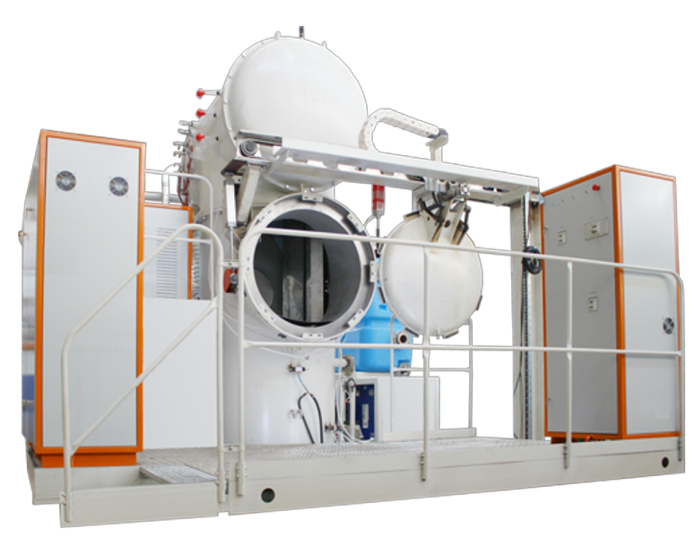
Vacuum furnace for heat treatment "1SNV-5.10.5/11.5F" is designed for heat treatment of products - tempering, annealing, aging, etc. with quenching in oil.
It is possible to cool products in an inert gas.
The furnace "1SNV-5.10.5/11.5F" consists of units:
1) Heating chamber.
2) Quenching chamber.
3) Back cover.
4) Cover with fan.
5) Loading door.
7) Under.
8) Vacuum system.
9) Pneumatic system.
10) Water cooling system.
11) Electrical wiring.
12) Oil supply system.
13) Overpass.
14) Service platform.
15) Control system.
Heating chamber.
The cylindrical heating chamber is made of sheet structural steel. A flange for attaching the cover is welded to the end of the cylinder. The chamber has a water cooling jacket divided into 3 zones. Branch pipes are welded into the chamber for installing thermocouples, current leads and connecting to the vacuum system. The chamber is equipped with a flange for connecting to the hardening chamber. A heating unit with a rotary damper is installed inside the chamber. The heating unit is a welded rectangular frame with pins installed on the side walls. Ceramic insulators for the heaters are hung on the pins. The furnace has 3 heaters made of heat-resistant alloy.
The rotary damper is a structure made of a metal frame and two-layer ceramic fiber insulation. It serves to protect the furnace chambers and the mechanism for vertical movement of the charge from thermal radiation when the product with the hearth is removed from the heating chamber. The damper is driven by a pneumatic cylinder and rotates 900, closing and opening the opening. When the product is in the heating chamber, the damper rotates perpendicularly downwards, protection from thermal radiation at this moment should be provided by the sub.
The sealing of the connector between the flanges of the heating chamber and the hardening chamber is made with an elastic end seal.
Hardening chamber.
The oil hardening chamber has pipes for loading and unloading the product and for installing the cover with a fan. The loading door is made sliding on the portal, the direction of movement is perpendicular to the axis of the heating chamber. On the body of the hardening chamber there is a bayonet lock, fixing the sliding door to the hardening chamber during the process, pressing under the lock ring is performed using a pneumatic drive. The rotation of the bayonet ring is provided by an electric motor.
The hardening chamber is filled with oil for vacuum hardening. The mechanism for moving the charge is also installed in the lower chamber, it has a chain design and serves to move the product between the loading-heating-hardening-unloading positions. The supporting structure of the mechanism - a metal frame is connected to the wall of the hardening chamber. The speed of movement of the platform with the product is 7.2 m / min. The design positions of the platform are fixed by a signal from the limit switches.
Using a loader, the charge is installed on the hearth in the hardening chamber and then moved for heating and hardening. The hearth consists of a support table and a cover
The support table and the cover are made of heat-resistant alloy and contact each other through a limited surface area in order to reduce heat transfer.
Back cover.
The cover is designed to remove the heat block from the chamber, and is made of two rolled bottoms welded on a flange. A vacuum seal is laid in the flange groove. The bottoms are made of structural steel.
Cover with a fan.
The cover with a fan provides the ability to cool in an inert gas environment and turn on the impeller of the centrifugal fan and the spiral tubular gas-water heat exchanger.
Loading door.
The loading door is made sliding on the portal, the direction of movement is perpendicular to the axis of the heating chamber. The sliding door to the hardening chamber is fixed with a bayonet lock during the process.
Mechanism for vertical movement of the charge.
The mechanism for vertical movement of the charge moves the processed products together with the necessary equipment between the loading-heating-hardening positions in the interior of the heating and hardening chambers. The product is installed using a loader on the undercarriage.
Underbody.
Underbody is located on the carriage of the vertical movement mechanism of the charge and cuts off the internal space of the thermal block from the heating chamber when the product is in the heating position.
Vacuum system.
The vacuum system is designed to create a vacuum in the chambers of the installation. The system is a set of devices for creating a vacuum and pipelines connecting them through vacuum angle valves and a bypass line with the pumped out volume.
The system consists of a combined line of forevacuum pumping and creating a high vacuum. Forevacuum pumping is created by Roots type pumps and a slide valve. High vacuum pumping is performed by an oil booster pump. The necessary pneumatic valves are installed on the line. The vacuum system has a sufficient number of sensors for measuring medium and high vacuum. There is an argon inlet valve on the vacuum pipeline (enables accelerated cooling of the product in an inert gas).
Pneumatic system.
The pneumatic system is designed to control the pneumatic drives of vacuum valves. The pneumatic system includes an air preparation unit, pneumatic distributors and the necessary supply lines.
Water cooling system.
The water cooling system is designed to supply and drain water required for cooling the vacuum system pumps, cooling the quenching oil, heating and quenching chambers, the rear cover and the loading door.
The water cooling system is divided into two circuits and consists of a pressure and drain manifold, a storage tank and a circulating water cooling system with a detachable plate heat exchanger.
The water cooling system is connected to the workshop water supply system and has a supply water temperature of no more than 18-20 °C. Water flow through the channels is monitored by liquid flow sensors that monitor the water flow at the outlet. If there is no water at the drain, an alarm signal is generated.
Electrical wiring.
The electrical wiring is designed to supply power to the heating chamber current leads, transformers, electric motors, pneumatic valves, and consists of a busbar, harnesses with electric wires, the necessary protective covers and boxes.
Oil supply system.
The oil supply system is used to cool the quenching medium by circulating it through an external water-oil heat exchanger using a gear pump.
Overpass.
The overpass is designed to organize the loading and unloading of products into the furnace with the ability to visually monitor this process, as well as for the installation and maintenance of the power cabinet, control cabinet and operator cabinet. Electrical wiring boxes are located under the overpass.
Maintenance platform.
The maintenance platform is designed to install and service the transformer unit, as well as to carry out periodic maintenance of mechanical units and systems.
Control system.
The unit is controlled from the front panels:
– power cabinet;
– control cabinet;
– operator cabinet.
The vacuum system and mechanism controls are located on the mnemonic diagram located on the front panel of the control cabinet. The heating controls are on the front panel of the personal computer.
The unit is equipped with a two-level control system that ensures the technological process is carried out in setup, manual, and automatic modes.
A logical programmable controller is used at the lower level of the control system.
The application program ensures:
– in setup mode – control of the mechanisms and devices of the unit subsystems (vacuum, heating, movement of mechanisms) for performing setup, repair and maintenance work;
– in manual mode – control of heating in the event of a failure in the automatic mode;
– in automated mode – an automated cycle of unit operation subject to permission from the PC.
The upper level is an industrial computer (PC).
The upper level software provides a graphical multi-window interface with the dispatcher; intelligent support of control functions:
– display of the status of mechanisms and sensors on the PC screen;
– indication of the current parameters of the unit in real time;
– input and correction of parameters, display of the "history" of the values of the unit parameters;
– automatic generation of database records, conversion of the generated database into the formats of the most commonly used systems for working with databases;
– fast run in the forward and reverse directions.
The lower level – a programmable logic controller (PLC) ensures the collection and processing of information from temperature and position sensors. Each controlled parameter at the stage of its determination is subject to standard mathematical processing, which includes: scaling of measured signals, control of the reliability of logical analysis of the values of interrelated parameters, rejection of false measurements, control of violation of the specified measurement range.
The heating controller ensures regulation of the heating circuits of the zone along the program trajectory.
The technical means of the lower level ensure autonomous operation of the control system without the upper level.
All manual control signals are implemented through a controller that monitors manual actions, taking them into account during automated control and diagnostics, correcting operator errors.
Heating is controlled using a thyristor power controller.
Power control in manual mode of heating zones is performed by setting the setting from the front panel of thyristor power controllers located in the transformer block, and in automated mode from the controller.
It is possible to cool products in an inert gas.
The furnace "1SNV-5.10.5/11.5F" consists of units:
1) Heating chamber.
2) Quenching chamber.
3) Back cover.
4) Cover with fan.
5) Loading door.
7) Under.
8) Vacuum system.
9) Pneumatic system.
10) Water cooling system.
11) Electrical wiring.
12) Oil supply system.
13) Overpass.
14) Service platform.
15) Control system.
Heating chamber.
The cylindrical heating chamber is made of sheet structural steel. A flange for attaching the cover is welded to the end of the cylinder. The chamber has a water cooling jacket divided into 3 zones. Branch pipes are welded into the chamber for installing thermocouples, current leads and connecting to the vacuum system. The chamber is equipped with a flange for connecting to the hardening chamber. A heating unit with a rotary damper is installed inside the chamber. The heating unit is a welded rectangular frame with pins installed on the side walls. Ceramic insulators for the heaters are hung on the pins. The furnace has 3 heaters made of heat-resistant alloy.
The rotary damper is a structure made of a metal frame and two-layer ceramic fiber insulation. It serves to protect the furnace chambers and the mechanism for vertical movement of the charge from thermal radiation when the product with the hearth is removed from the heating chamber. The damper is driven by a pneumatic cylinder and rotates 900, closing and opening the opening. When the product is in the heating chamber, the damper rotates perpendicularly downwards, protection from thermal radiation at this moment should be provided by the sub.
The sealing of the connector between the flanges of the heating chamber and the hardening chamber is made with an elastic end seal.
Hardening chamber.
The oil hardening chamber has pipes for loading and unloading the product and for installing the cover with a fan. The loading door is made sliding on the portal, the direction of movement is perpendicular to the axis of the heating chamber. On the body of the hardening chamber there is a bayonet lock, fixing the sliding door to the hardening chamber during the process, pressing under the lock ring is performed using a pneumatic drive. The rotation of the bayonet ring is provided by an electric motor.
The hardening chamber is filled with oil for vacuum hardening. The mechanism for moving the charge is also installed in the lower chamber, it has a chain design and serves to move the product between the loading-heating-hardening-unloading positions. The supporting structure of the mechanism - a metal frame is connected to the wall of the hardening chamber. The speed of movement of the platform with the product is 7.2 m / min. The design positions of the platform are fixed by a signal from the limit switches.
Using a loader, the charge is installed on the hearth in the hardening chamber and then moved for heating and hardening. The hearth consists of a support table and a cover
The support table and the cover are made of heat-resistant alloy and contact each other through a limited surface area in order to reduce heat transfer.
Back cover.
The cover is designed to remove the heat block from the chamber, and is made of two rolled bottoms welded on a flange. A vacuum seal is laid in the flange groove. The bottoms are made of structural steel.
Cover with a fan.
The cover with a fan provides the ability to cool in an inert gas environment and turn on the impeller of the centrifugal fan and the spiral tubular gas-water heat exchanger.
Loading door.
The loading door is made sliding on the portal, the direction of movement is perpendicular to the axis of the heating chamber. The sliding door to the hardening chamber is fixed with a bayonet lock during the process.
Mechanism for vertical movement of the charge.
The mechanism for vertical movement of the charge moves the processed products together with the necessary equipment between the loading-heating-hardening positions in the interior of the heating and hardening chambers. The product is installed using a loader on the undercarriage.
Underbody.
Underbody is located on the carriage of the vertical movement mechanism of the charge and cuts off the internal space of the thermal block from the heating chamber when the product is in the heating position.
Vacuum system.
The vacuum system is designed to create a vacuum in the chambers of the installation. The system is a set of devices for creating a vacuum and pipelines connecting them through vacuum angle valves and a bypass line with the pumped out volume.
The system consists of a combined line of forevacuum pumping and creating a high vacuum. Forevacuum pumping is created by Roots type pumps and a slide valve. High vacuum pumping is performed by an oil booster pump. The necessary pneumatic valves are installed on the line. The vacuum system has a sufficient number of sensors for measuring medium and high vacuum. There is an argon inlet valve on the vacuum pipeline (enables accelerated cooling of the product in an inert gas).
Pneumatic system.
The pneumatic system is designed to control the pneumatic drives of vacuum valves. The pneumatic system includes an air preparation unit, pneumatic distributors and the necessary supply lines.
Water cooling system.
The water cooling system is designed to supply and drain water required for cooling the vacuum system pumps, cooling the quenching oil, heating and quenching chambers, the rear cover and the loading door.
The water cooling system is divided into two circuits and consists of a pressure and drain manifold, a storage tank and a circulating water cooling system with a detachable plate heat exchanger.
The water cooling system is connected to the workshop water supply system and has a supply water temperature of no more than 18-20 °C. Water flow through the channels is monitored by liquid flow sensors that monitor the water flow at the outlet. If there is no water at the drain, an alarm signal is generated.
Electrical wiring.
The electrical wiring is designed to supply power to the heating chamber current leads, transformers, electric motors, pneumatic valves, and consists of a busbar, harnesses with electric wires, the necessary protective covers and boxes.
Oil supply system.
The oil supply system is used to cool the quenching medium by circulating it through an external water-oil heat exchanger using a gear pump.
Overpass.
The overpass is designed to organize the loading and unloading of products into the furnace with the ability to visually monitor this process, as well as for the installation and maintenance of the power cabinet, control cabinet and operator cabinet. Electrical wiring boxes are located under the overpass.
Maintenance platform.
The maintenance platform is designed to install and service the transformer unit, as well as to carry out periodic maintenance of mechanical units and systems.
Control system.
The unit is controlled from the front panels:
– power cabinet;
– control cabinet;
– operator cabinet.
The vacuum system and mechanism controls are located on the mnemonic diagram located on the front panel of the control cabinet. The heating controls are on the front panel of the personal computer.
The unit is equipped with a two-level control system that ensures the technological process is carried out in setup, manual, and automatic modes.
A logical programmable controller is used at the lower level of the control system.
The application program ensures:
– in setup mode – control of the mechanisms and devices of the unit subsystems (vacuum, heating, movement of mechanisms) for performing setup, repair and maintenance work;
– in manual mode – control of heating in the event of a failure in the automatic mode;
– in automated mode – an automated cycle of unit operation subject to permission from the PC.
The upper level is an industrial computer (PC).
The upper level software provides a graphical multi-window interface with the dispatcher; intelligent support of control functions:
– display of the status of mechanisms and sensors on the PC screen;
– indication of the current parameters of the unit in real time;
– input and correction of parameters, display of the "history" of the values of the unit parameters;
– automatic generation of database records, conversion of the generated database into the formats of the most commonly used systems for working with databases;
– fast run in the forward and reverse directions.
The lower level – a programmable logic controller (PLC) ensures the collection and processing of information from temperature and position sensors. Each controlled parameter at the stage of its determination is subject to standard mathematical processing, which includes: scaling of measured signals, control of the reliability of logical analysis of the values of interrelated parameters, rejection of false measurements, control of violation of the specified measurement range.
The heating controller ensures regulation of the heating circuits of the zone along the program trajectory.
The technical means of the lower level ensure autonomous operation of the control system without the upper level.
All manual control signals are implemented through a controller that monitors manual actions, taking them into account during automated control and diagnostics, correcting operator errors.
Heating is controlled using a thyristor power controller.
Power control in manual mode of heating zones is performed by setting the setting from the front panel of thyristor power controllers located in the transformer block, and in automated mode from the controller.
Technical data
Rated power, kW
152
Heating chamber power, kW
102
Idle power, kW
61
Working space dimensions (L*W*H), mm
1000*500*500
Maximum residual pressure in a cold state, mmHg.
10-3
Leakage value, l µm Hg/s
5
Loading weight, kg
200
Uniformity of the temperature field, °C
±5
Maximal temperature, °C
1150
Supply voltage, V
400
Frequency, Hz
50
Number of heater phases
3
Number of thermal control zones
2
Overall dimensions (L*W*H), mm
6500*4700*5300
Weight, kg
5.2
Cooling water consumption, m3/h
15
Detailed information PDF
Submit an inquiry
Прошлое
Настоящее
Будущее