
 Personal Account


 Личный Кабинет

The Heat Treatment Unit "ETA-10" for Long Aluminum Alloy Parts

The Heat Treatment Unit "ETA-10" for Long Aluminum Alloy Parts
Description
Heat treatment unit "ETA-10"
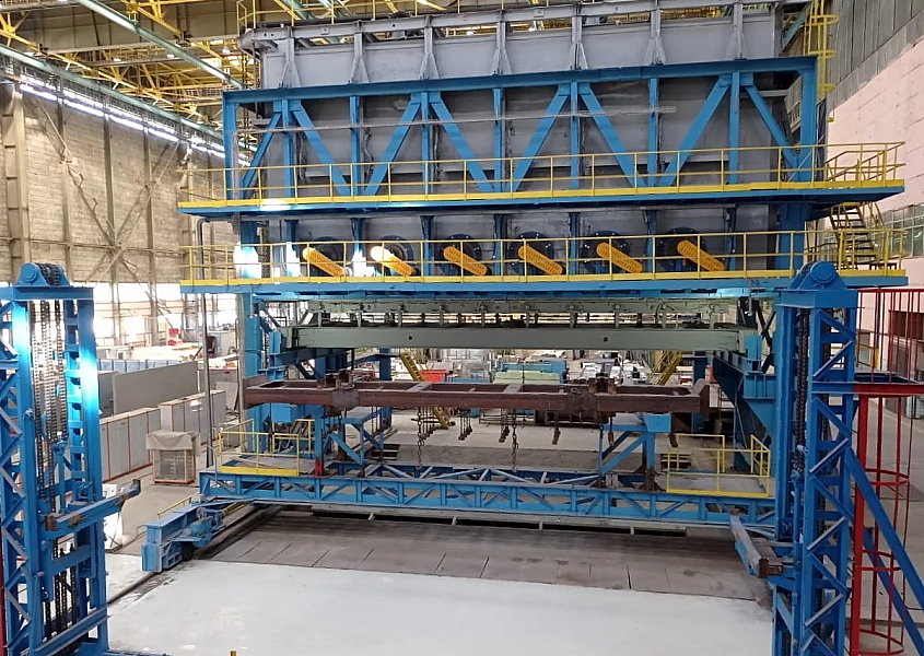
The heat treatment unit "ETA-10" for long aluminum alloy parts is designed for heat treatment of aluminum alloy parts up to 10 m long, 2.2 m wide, and weighing up to 3,000 kg.
The unit performes heat treatments such as quenching and annealing (full and short). The unit operates by creating specific thermal conditions for heating parts in an electric furnace using forced air circulation and subsequent cooling, depending on the type of heat treatment.
Furnace Components
1. Loading/Unloading Mechanism
2. Quenching Tank
3. Operator Station
4. Electrical Wiring
5. Resistor Block
6. Thermocouple Locations
7. Electric Circulation Furnace for the ETA-10 Unit
8. Fan Installation
9. Pneumatic System
10. Heating Element Block
11. Lid Lift Mechanism
12. Left Bottom Drive
13. Right Bottom Drive
14. Heating Cabinet for Sections 1-6
15. Heating Cabinet for Sections 7-12
16. Mechanism Control Cabinet 1
17. Mechanism Control Cabinet 2
18. Control Panel 1
19. Control Panel 2
Design and Operation of the Unit and Its Components
The core of the electrothermal unit is an electric circulation furnace with a loading opening for heating the parts to be heat treated in a charge. The parts are heated by circulating heated air generated by a fan. The air is heated by resistive heating elements.
The electric circulation furnace consists of the following components:
- furnace frame;
- heating elements;
- fan assembly;
- furnace rack;
- loading and unloading mechanism.
The outer and inner furnace frames are welded, sealed, and constructed from separate modular sections.
The heaters are separated from the furnace workspace by removable metal screens. The space between the inner frame and the screens heats the circulating air. Air circulation within the furnace is carried out from top to bottom by centrifugal fans. The furnace temperature is regulated by thermocouples located vertically near the heaters. Maintenance areas for the heating element and thermocouple terminals are located in three tiers around the furnace.
The fan unit, which circulates air inside the furnace, consists of an impeller, a bearing assembly with oil bath cooling, and an electric motor.
There are 12 fan units in total (6 on each side). Each fan unit is mounted on its own frame, which in turn is attached to the furnace trestle platform.
A retractable hearth is used to close and seal the furnace working opening. The hearth consists of a sliding frame, a hearth cover, a clamping mechanism, and a cover.
Furnace trestle.
The trestle contains three tiers of platforms from which the terminals of the heating elements, thermocouples, and other mechanisms are serviced. A rail track is installed on the trestle under the furnace opening for moving the retractable hearth.
The loading and unloading mechanism is used for vertical movement of the charge and is used during the quenching process. The workpiece is suspended by chains on a crossbar mounted on the brackets of the transport trolley.
A mechanized transport trolley for transporting loaded workpieces from the loading/unloading area to the furnace.
The quenching tank is a sealed welded sheet steel structure reinforced with rolled steel ribs. The tank is installed in a pit beneath the furnace. A bubbler is located at the bottom of the tank to mix the liquid with air. The tank includes a pump station and pipelines with shut-off valves, including a water overflow outlet when the workpiece is immersed in the working fluid.
The pneumatic system includes an air preparation unit, a pneumatic distributor panel, and pipelines. The system is designed to control the pneumatic drives of the hearth clamping mechanism.
The electrical wiring is designed to supply power to electric heaters, fan motors, moving mechanism motors, drive units, as well as control circuits from units, control panels, heating cabinets, and control cabinets. It consists of busbars, harnesses with electric drives, protective covers, and boxes.
Control cabinet 1-2 is used to connect the power lines to the unit. The front panel of the cabinet contains phase and network indicators, an emergency stop button, on/off buttons for the trolley drive mechanisms, the sliding hearth, and the tank doors, and a PC monitor displaying a visualization of the process.
Heating cabinets 1-6 and 7-12 are used to connect the power lines to the unit. The front panel of the cabinet contains phase and network indicators, an on/off button, and an emergency stop button.
The stationary control panel (Control Panel 1) is located next to the unit in the operator's work area. The control panel's front panel contains controls for the trolley, hearth, and door mechanisms, as well as an emergency stop button. A monitor is built into the housing to display images from video cameras in the blind spots of the moving mechanisms.
The portable handheld control panel (Control Panel 2) can be positioned conveniently for the operator. The control panel's front panel contains two buttons for raising and lowering the winch.
The unit performes heat treatments such as quenching and annealing (full and short). The unit operates by creating specific thermal conditions for heating parts in an electric furnace using forced air circulation and subsequent cooling, depending on the type of heat treatment.
Furnace Components
1. Loading/Unloading Mechanism
2. Quenching Tank
3. Operator Station
4. Electrical Wiring
5. Resistor Block
6. Thermocouple Locations
7. Electric Circulation Furnace for the ETA-10 Unit
8. Fan Installation
9. Pneumatic System
10. Heating Element Block
11. Lid Lift Mechanism
12. Left Bottom Drive
13. Right Bottom Drive
14. Heating Cabinet for Sections 1-6
15. Heating Cabinet for Sections 7-12
16. Mechanism Control Cabinet 1
17. Mechanism Control Cabinet 2
18. Control Panel 1
19. Control Panel 2
Design and Operation of the Unit and Its Components
The core of the electrothermal unit is an electric circulation furnace with a loading opening for heating the parts to be heat treated in a charge. The parts are heated by circulating heated air generated by a fan. The air is heated by resistive heating elements.
The electric circulation furnace consists of the following components:
- furnace frame;
- heating elements;
- fan assembly;
- furnace rack;
- loading and unloading mechanism.
The outer and inner furnace frames are welded, sealed, and constructed from separate modular sections.
The heaters are separated from the furnace workspace by removable metal screens. The space between the inner frame and the screens heats the circulating air. Air circulation within the furnace is carried out from top to bottom by centrifugal fans. The furnace temperature is regulated by thermocouples located vertically near the heaters. Maintenance areas for the heating element and thermocouple terminals are located in three tiers around the furnace.
The fan unit, which circulates air inside the furnace, consists of an impeller, a bearing assembly with oil bath cooling, and an electric motor.
There are 12 fan units in total (6 on each side). Each fan unit is mounted on its own frame, which in turn is attached to the furnace trestle platform.
A retractable hearth is used to close and seal the furnace working opening. The hearth consists of a sliding frame, a hearth cover, a clamping mechanism, and a cover.
Furnace trestle.
The trestle contains three tiers of platforms from which the terminals of the heating elements, thermocouples, and other mechanisms are serviced. A rail track is installed on the trestle under the furnace opening for moving the retractable hearth.
The loading and unloading mechanism is used for vertical movement of the charge and is used during the quenching process. The workpiece is suspended by chains on a crossbar mounted on the brackets of the transport trolley.
A mechanized transport trolley for transporting loaded workpieces from the loading/unloading area to the furnace.
The quenching tank is a sealed welded sheet steel structure reinforced with rolled steel ribs. The tank is installed in a pit beneath the furnace. A bubbler is located at the bottom of the tank to mix the liquid with air. The tank includes a pump station and pipelines with shut-off valves, including a water overflow outlet when the workpiece is immersed in the working fluid.
The pneumatic system includes an air preparation unit, a pneumatic distributor panel, and pipelines. The system is designed to control the pneumatic drives of the hearth clamping mechanism.
The electrical wiring is designed to supply power to electric heaters, fan motors, moving mechanism motors, drive units, as well as control circuits from units, control panels, heating cabinets, and control cabinets. It consists of busbars, harnesses with electric drives, protective covers, and boxes.
Control cabinet 1-2 is used to connect the power lines to the unit. The front panel of the cabinet contains phase and network indicators, an emergency stop button, on/off buttons for the trolley drive mechanisms, the sliding hearth, and the tank doors, and a PC monitor displaying a visualization of the process.
Heating cabinets 1-6 and 7-12 are used to connect the power lines to the unit. The front panel of the cabinet contains phase and network indicators, an on/off button, and an emergency stop button.
The stationary control panel (Control Panel 1) is located next to the unit in the operator's work area. The control panel's front panel contains controls for the trolley, hearth, and door mechanisms, as well as an emergency stop button. A monitor is built into the housing to display images from video cameras in the blind spots of the moving mechanisms.
The portable handheld control panel (Control Panel 2) can be positioned conveniently for the operator. The control panel's front panel contains two buttons for raising and lowering the winch.
Technical data
Power supply voltage, V
400
Rated frequency, Hz
50
Phases
3
Dimensions of the furnace operating space (L*W*H), mm
11700*2000*3500
Maximal product dimensions (L*W*H), mm
10000*1200*2500
Loading mechanism winch lifting capacity, kgf
5000
Maximal charge weight, kgf
3000
Installed capacity, kW
1390
Furnace thermal power, kW
1080
Electrical group power, kW
90
Number of electrical groups, units
12
Operating temperature, ºC
350 - 550
Maximal furnace temperature, ºC
600±5
Furnace temperature control
Automatic
Part heating time, min
60
Holding time, min
10 - 180
Number of fans
12
Quenching medium temperature (water or organic compound solutions), ºC
+10 - +40
Lowering time of charge in quenching tank, s
15
Heat release in workshop, kcal/h
390000
Quenching tank capacity, m3
80
Water volume filled into tank, m3
75
Overall furnace dimensions (with quenching tank), (L*W*H), mm
18100*7000*18500
Submit an inquiry
Прошлое
Настоящее
Будущее