
 Personal Account


 Личный Кабинет

Vacuum thermal furnace “PVV-1300”

Vacuum thermal furnace “PVV-1300”
Description
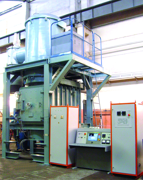
Vacuum thermal furnace “PVV-1300” for heat treatment, hardening, soldering, tempering and annealing
 Detailed information PDF
1. Purpose. Used technological processes.
The vacuum thermal furnace “PVV-1300” is designed for homogenizing parts made of heat-resistant alloys, hardening, soldering, tempering and annealing after heat treatment.
The operation of the furnace is to heat the workpiece in a vacuum to a certain temperature, hold it at this temperature, move the product to the lower chamber and cool it in an inert gas environment.
2. Features. The physical processes used.
Chamber heat treatment furnaces “PVV-1300” are suitable for heat treatment of medium and small parts.
3. Construction.
The furnace includes the following main components:
- Heating chamber,
- Cooling chamber,
- Technological shutter,
- Cage lift,
- Trolley for moving the heat exchanger during repair work,
- Device for moving the cage with a lift to the loading table of the furnace,
- Water-cooling system,
- Pneumatic system,
- Vacuum system,
- Inert gas supply system,
- Electrical wiring.
3.1 Heating chamber.
The heating chamber body is a vacuum chamber ща 1650*2550 mm (diameter*height) with a water-cooled jacket. Heater material - graphite. The heating chamber is equipped with a rigid thermal insulation lining made of carbon composite material.
3.2 Cooling chamber.
The cooling chamber body is a parallelepiped form 1600*2500*1700 mm (width*length*height). The chamber is equipped with a fan, a heat exchanger, a system of screens directing the gas flow, and a hatch for loading and unloading the cage. A sealed heat-insulating seal installed between the heating chamber and the cooling chamber.
3.3 Technological gate.
The technological shutter intended for vacuum-tight isolation of the heating chamber from the cooling chamber and for thermal insulation, which ensures blocking of the heat flow from the heating chamber to the cooling chamber and allows reducing the cooling time of the charge.
3.4 Cage lift.
The cage is moved from the cooling chamber to the heating chamber and back by a lift driven by a pneumatic drive.
3.5 Heat exchanger moving trolley.
The heat exchanger moving cart is used to move the fan and heat exchanger assembly out of the cooling chamber during repair work.
3.6 Device for moving the cage with a lift to the loading table of the furnace.
Loading of the cage into the chamber is carried out using a device for moving the cage, which includes a rail track and a trolley with a mechanical lifting mechanism.
3.7 Water-cooling system.
The water-cooling system provides supply and drainage of water necessary for cooling the heating chamber jackets and cooling chamber pipelines, as well as for cooling vacuum pump systems during the heat treatment regime and transformer cabinet equipment.
The water cooling system is connected to the workshop water supply system. The water flow through the channels is monitored by water control units complete with water control sensors that monitor the water flow at the outlet. An alarm signal appears when water flow fails.
3.8 Pneumatic system.
The pneumatic system ensures the control of the pneumatic drives of vacuum valves and pneumatic cylinders of the process valve and the cage lifting and lowering system
3.9 Vacuum system.
The vacuum system makes vacuum in the heating and cooling chambers. The system consists of a forevacuum pumping line and a high vacuum line. On a vacuum system, all valves are pneumatically actuated.
3.10 Inert gas supply system.
Inert gas system supplies high-purity inert argon gas to the heating chamber and cooling chamber. It consists of a receiver, flow meter cabinet and pipeline fittings.
3.11 Electrical wiring.
The electrical wiring passes the power from the power cabinet to the units and systems of the plant.
3.12 Control system.
The control system (CS) is based on modern computer technology and integrates the entire flow of information: organizing an interface with the operator-technologist; series-parallel control of vacuum system mechanisms; software control of the heating process; identification of the state of the technological system; documenting the technological process (archiving).
The operation of the system at the lower level is controlled by the controller, and at the upper level - by an industrial computer with a touch screen.
The control system ensures operation of the furnace in the following modes:
- "Manual control";
- “Programming”;
- “Automated”.
The “Manual control” mode provides control of the installation subsystems (vacuum, heating) from the control panel to complete the heat treatment cycle in the event of a failure of the automated mode.
In the “Programming” mode, you can enter the values of technological parameters that ensure the heat treatment process: heat treatment program (number of sections, temperature, heating rate and processing time), permissible range of working vacuum.
In the “Automated” mode, the implementation of macro commands for the heat treatment process is ensured.
Installation control panel:
- implemented on the basis of an industrial computer with a touch screen;
- is geographically located near the furnace and includes a mnemonic diagram that displays the state of the vacuum system and heating system.
The control panel displays digitally the main parameters of the vacuum heat treatment process:
- pressure in the chamber;
- pressure in vacuum pumps;
- temperature in the heating chamber.
The industrial computer provides all the services necessary for work:
- multi-window ergonomic user interface with color three-dimensional graphics;
- effective system support for all application processes;
- recording a report on the progress of the technological process; the report file can be called up on the monitor for visual analysis or printed in digital and graphical form.
The control system has the ability to record and store all technological process parameters with the ability to output to a printer:
- current time;
- temperature;
- pressure in the chambers;
- leakage.
To ensure safe operation of the installation and operating personnel, and to prevent incorrect operator actions, the necessary vacuum and cooling interlocks have been implemented. Protection against unauthorized access to settings parameters and the process program is provided.
The control system provides input/output of passport data for the technological process, product number and code, date and time of heat treatment, automatic registration of heat treatment and soldering modes with archiving of parameters, as well as registration and viewing of technological process parameters in graphical form and visual control .
The period for storing technological parameters of the technological process is at least once every 5 minutes. The number of control programs is at least 50. It is possible to control several furnaces from one computer.
3.2 Equipment advantages.
Advantages of vacuum heat treatment: absence of oxidation and decarburization, reduction in the degree of warping of parts, high equipment flexibility, increased process productivity, high environmental friendliness and safety of processes, improved thermal production culture.
The vacuum thermal furnace “PVV-1300” is designed for homogenizing parts made of heat-resistant alloys, hardening, soldering, tempering and annealing after heat treatment.
The operation of the furnace is to heat the workpiece in a vacuum to a certain temperature, hold it at this temperature, move the product to the lower chamber and cool it in an inert gas environment.
2. Features. The physical processes used.
Chamber heat treatment furnaces “PVV-1300” are suitable for heat treatment of medium and small parts.
3. Construction.
The furnace includes the following main components:
- Heating chamber,
- Cooling chamber,
- Technological shutter,
- Cage lift,
- Trolley for moving the heat exchanger during repair work,
- Device for moving the cage with a lift to the loading table of the furnace,
- Water-cooling system,
- Pneumatic system,
- Vacuum system,
- Inert gas supply system,
- Electrical wiring.
3.1 Heating chamber.
The heating chamber body is a vacuum chamber ща 1650*2550 mm (diameter*height) with a water-cooled jacket. Heater material - graphite. The heating chamber is equipped with a rigid thermal insulation lining made of carbon composite material.
3.2 Cooling chamber.
The cooling chamber body is a parallelepiped form 1600*2500*1700 mm (width*length*height). The chamber is equipped with a fan, a heat exchanger, a system of screens directing the gas flow, and a hatch for loading and unloading the cage. A sealed heat-insulating seal installed between the heating chamber and the cooling chamber.
3.3 Technological gate.
The technological shutter intended for vacuum-tight isolation of the heating chamber from the cooling chamber and for thermal insulation, which ensures blocking of the heat flow from the heating chamber to the cooling chamber and allows reducing the cooling time of the charge.
3.4 Cage lift.
The cage is moved from the cooling chamber to the heating chamber and back by a lift driven by a pneumatic drive.
3.5 Heat exchanger moving trolley.
The heat exchanger moving cart is used to move the fan and heat exchanger assembly out of the cooling chamber during repair work.
3.6 Device for moving the cage with a lift to the loading table of the furnace.
Loading of the cage into the chamber is carried out using a device for moving the cage, which includes a rail track and a trolley with a mechanical lifting mechanism.
3.7 Water-cooling system.
The water-cooling system provides supply and drainage of water necessary for cooling the heating chamber jackets and cooling chamber pipelines, as well as for cooling vacuum pump systems during the heat treatment regime and transformer cabinet equipment.
The water cooling system is connected to the workshop water supply system. The water flow through the channels is monitored by water control units complete with water control sensors that monitor the water flow at the outlet. An alarm signal appears when water flow fails.
3.8 Pneumatic system.
The pneumatic system ensures the control of the pneumatic drives of vacuum valves and pneumatic cylinders of the process valve and the cage lifting and lowering system
3.9 Vacuum system.
The vacuum system makes vacuum in the heating and cooling chambers. The system consists of a forevacuum pumping line and a high vacuum line. On a vacuum system, all valves are pneumatically actuated.
3.10 Inert gas supply system.
Inert gas system supplies high-purity inert argon gas to the heating chamber and cooling chamber. It consists of a receiver, flow meter cabinet and pipeline fittings.
3.11 Electrical wiring.
The electrical wiring passes the power from the power cabinet to the units and systems of the plant.
3.12 Control system.
The control system (CS) is based on modern computer technology and integrates the entire flow of information: organizing an interface with the operator-technologist; series-parallel control of vacuum system mechanisms; software control of the heating process; identification of the state of the technological system; documenting the technological process (archiving).
The operation of the system at the lower level is controlled by the controller, and at the upper level - by an industrial computer with a touch screen.
The control system ensures operation of the furnace in the following modes:
- "Manual control";
- “Programming”;
- “Automated”.
The “Manual control” mode provides control of the installation subsystems (vacuum, heating) from the control panel to complete the heat treatment cycle in the event of a failure of the automated mode.
In the “Programming” mode, you can enter the values of technological parameters that ensure the heat treatment process: heat treatment program (number of sections, temperature, heating rate and processing time), permissible range of working vacuum.
In the “Automated” mode, the implementation of macro commands for the heat treatment process is ensured.
Installation control panel:
- implemented on the basis of an industrial computer with a touch screen;
- is geographically located near the furnace and includes a mnemonic diagram that displays the state of the vacuum system and heating system.
The control panel displays digitally the main parameters of the vacuum heat treatment process:
- pressure in the chamber;
- pressure in vacuum pumps;
- temperature in the heating chamber.
The industrial computer provides all the services necessary for work:
- multi-window ergonomic user interface with color three-dimensional graphics;
- effective system support for all application processes;
- recording a report on the progress of the technological process; the report file can be called up on the monitor for visual analysis or printed in digital and graphical form.
The control system has the ability to record and store all technological process parameters with the ability to output to a printer:
- current time;
- temperature;
- pressure in the chambers;
- leakage.
To ensure safe operation of the installation and operating personnel, and to prevent incorrect operator actions, the necessary vacuum and cooling interlocks have been implemented. Protection against unauthorized access to settings parameters and the process program is provided.
The control system provides input/output of passport data for the technological process, product number and code, date and time of heat treatment, automatic registration of heat treatment and soldering modes with archiving of parameters, as well as registration and viewing of technological process parameters in graphical form and visual control .
The period for storing technological parameters of the technological process is at least once every 5 minutes. The number of control programs is at least 50. It is possible to control several furnaces from one computer.
3.2 Equipment advantages.
Advantages of vacuum heat treatment: absence of oxidation and decarburization, reduction in the degree of warping of parts, high equipment flexibility, increased process productivity, high environmental friendliness and safety of processes, improved thermal production culture.
Technical data
Dimensions of the heating chamber (Ø*H), mm
900*900
Maximal heating temperature, °C
1350
Cage weight including equipment with pallet, kg
900
Temperature measurement accuracy, °C
±0,1
Time to raise the oven temperature from room temperature to 1240 °C without loading, min
45
Temperature uniformity in the working space without charge from 500 to 1300, °C
+5
Operating pressure with gas carrier, mmHg
from 10-2 to 500
Ultimate vacuum in the heating chamber in a cold state, without loading, mmHg
5*10-5
Time of evacuation of the heating chamber and cooling chamber simultaneously to a residual pressure of 5*10-1 mmHg without loading, min
15
Evacuation time of the cooling chamber to a residual pressure of 5*10-2 mmHg, min
15
Cage cooling rate, °C/min
60-100
Overall dimensions (L*W*H), mm
8955*6900*7915
Weight, kg
16000
Detailed information PDF
Submit an inquiry
Прошлое
Настоящее
Будущее