
 Personal Account


 Личный Кабинет

Vacuum vertical furnace "PVV-1250-12.5/12.5"

Vacuum vertical furnace "PVV-1250-12.5/12.5"
Description
Vacuum vertical furnace "PVV-1250-12.5/12.5" for heat treatment of products made of heat-resistant alloys
 Detailed information PDF
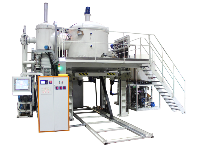
The vertical vacuum furnace "PVV-1250-12.5/12.5" is designed for heat treatment of products made of heat-resistant alloys.
The furnace consists of the main blocks and units:
1 Heating chamber,
2 Upper cover,
3 Self-propelled hearth,
4 Locking device,
5 Hearth lifting mechanism,
6 Trestle,
7 Rail track,
8 Vacuum system,
9 Water cooling system,
10 Pneumatic system,
11 Argon inlet system,
12 Electrical wiring,
13 Transformer unit,
14 Power cabinet,
15 Control cabinet,
16 Operator console,
17 Normalizer unit.
The furnace operates by heating the workpiece in a vacuum to the required temperature, holding it at this temperature and cooling it in an argon environment. Forced cooling of the assembly unit under the pressure of an inert atmosphere is achieved by forced circulation of argon inside the furnace: the working space of the furnace - the heat exchanger - the working space of the furnace.
1. Heating chamber.
The cylindrical heating chamber is made of sheet stainless steel. Flanges are welded for fastening on one side of the upper cover, and on the other - the lower cover.
The chamber has a water cooling jacket divided into 4 zones.
For the installation of thermocouples, current leads and the necessary valves, pipes are welded into the chamber.
The chamber is equipped with four support plates for installation on the overpass.
2. Upper and lower covers.
The upper cover is fixed to the chamber with bolts. The covers are made with an elastic end seal.
The upper cover is made of two rolled bottoms welded on a flange. made of stainless steel. The rotation of the fan impeller is carried out by a frequency electric drive, which allows changing the rotation frequency. The lower cover in the self-propelled hearth, like the upper cover, is made of two rolling bottoms, with a cooling jacket formed between the bottoms.
3. Self-propelled hearth.
The hearth design has 2 wheel pairs driven by a gear motor, allowing movement along the rail track.
For fixing the lower cover movement mechanism on four brackets and subsequent lifting, the cover has support surfaces with holes for pins.
4. Locking device.
The heating chamber body has a locking device that fixes the lower cover to the heating chamber during the process. bayonet lock driven by a gear motor.
A heat chamber with screen thermal insulation made of 6 layers of metal screens is installed inside the heating chamber. 3 belt heaters made of molybdenum alloy.
5. Hearth lifting mechanism.
The hearth lifting mechanism is designed to load and unload the product from the heating chamber. It is a structure of 4 vertical lead screws connected by a system of horizontal shafts and bevel gears, and a drive with an electric motor (gear motor) for moving the cover up and down. The mechanism is columns. The extreme positions of the lower cover are fixed by a signal from the limit switches. loading positions to the design position together with the batch - first along the track, and then using the hearth lifting mechanism.
6. Trestle.
The trestle is designed to service the attachments of the heating chamber, the locking device, the water cooling system manifold, the normalizer units and the transformer unit.
7. Track.
The track is designed to move the lower cover.
8. Vacuum system.
The vacuum system is designed to create a vacuum in the chamber. a set of devices for creating a vacuum and pipelines connecting them through vacuum angle valves and a bypass line with the pumped out volume.
The system consists of a combined forevacuum pumping line and high vacuum creation.
Forevacuum pumping is created by a Roots pump. The necessary pneumatic valves are installed on the line.
High vacuum pumping is performed by a diffusion pump and a mechanical pump.
The valves installed on the steam-oil pumps close automatically when the power is turned off, which prevents oil from being released from the pumps into the pipeline.
The vacuum system has the required number of sensors for measuring medium and high vacuum. The installation has an air preparation unit.
9. Water cooling system.
The water cooling system is designed to supply and drain water required to cool the furnace and vacuum pumps during the heat treatment mode.
The water cooling system is connected to the shop water supply system. Water flow through the channels is monitored by liquid flow sensors that monitor the water flow at the outlet. If there is no water at the drain, an alarm signal is generated.
10. Pneumatic system.
The pneumatic system is designed to control the pneumatic drives of the vacuum valves. The pneumatic system includes a compressor, an air preparation unit, pneumatic distributors and the necessary supply lines.
11. Argon inlet system.
Argon is supplied to the chamber using the argon inlet system.
The ventilation unit and heat exchanger in the upper cover are designed to cool the charge with an inert atmosphere.
The vacuum system is connected to the heating chamber.
A heat chamber is installed inside the chamber, which is a welded cylindrical frame. Thin-sheet screen thermal insulation and ceramic insulators for heaters made of molybdenum alloy are hung on the frame. The gaps in the screen protection are sealed with thermal insulation wool.
The receiver is part of the process equipment and is an integral part of the argon inlet system, which includes a receiver for storing argon, pipelines, shut-off and control valves, and is designed to ensure accelerated cooling of the charge with argon with forced convection during heat treatment of parts.
12. Electrical wiring is designed to provide power supply to the current leads of the heating chamber, transformers, electric motors, pneumatic valves and a hydraulic station, and consists of a busbar, harnesses with electric wires, the necessary protective casings and boxes.
14. Control system.
The power cabinet, control cabinet, and operator console are designed to ensure uninterrupted operation and control of the technological process performed in the furnace.
The vacuum furnace is controlled from the front panels:
- Power cabinet,
- Control cabinet,
- Operator console.
The furnace consists of the main blocks and units:
1 Heating chamber,
2 Upper cover,
3 Self-propelled hearth,
4 Locking device,
5 Hearth lifting mechanism,
6 Trestle,
7 Rail track,
8 Vacuum system,
9 Water cooling system,
10 Pneumatic system,
11 Argon inlet system,
12 Electrical wiring,
13 Transformer unit,
14 Power cabinet,
15 Control cabinet,
16 Operator console,
17 Normalizer unit.
The furnace operates by heating the workpiece in a vacuum to the required temperature, holding it at this temperature and cooling it in an argon environment. Forced cooling of the assembly unit under the pressure of an inert atmosphere is achieved by forced circulation of argon inside the furnace: the working space of the furnace - the heat exchanger - the working space of the furnace.
1. Heating chamber.
The cylindrical heating chamber is made of sheet stainless steel. Flanges are welded for fastening on one side of the upper cover, and on the other - the lower cover.
The chamber has a water cooling jacket divided into 4 zones.
For the installation of thermocouples, current leads and the necessary valves, pipes are welded into the chamber.
The chamber is equipped with four support plates for installation on the overpass.
2. Upper and lower covers.
The upper cover is fixed to the chamber with bolts. The covers are made with an elastic end seal.
The upper cover is made of two rolled bottoms welded on a flange. made of stainless steel. The rotation of the fan impeller is carried out by a frequency electric drive, which allows changing the rotation frequency. The lower cover in the self-propelled hearth, like the upper cover, is made of two rolling bottoms, with a cooling jacket formed between the bottoms.
3. Self-propelled hearth.
The hearth design has 2 wheel pairs driven by a gear motor, allowing movement along the rail track.
For fixing the lower cover movement mechanism on four brackets and subsequent lifting, the cover has support surfaces with holes for pins.
4. Locking device.
The heating chamber body has a locking device that fixes the lower cover to the heating chamber during the process. bayonet lock driven by a gear motor.
A heat chamber with screen thermal insulation made of 6 layers of metal screens is installed inside the heating chamber. 3 belt heaters made of molybdenum alloy.
5. Hearth lifting mechanism.
The hearth lifting mechanism is designed to load and unload the product from the heating chamber. It is a structure of 4 vertical lead screws connected by a system of horizontal shafts and bevel gears, and a drive with an electric motor (gear motor) for moving the cover up and down. The mechanism is columns. The extreme positions of the lower cover are fixed by a signal from the limit switches. loading positions to the design position together with the batch - first along the track, and then using the hearth lifting mechanism.
6. Trestle.
The trestle is designed to service the attachments of the heating chamber, the locking device, the water cooling system manifold, the normalizer units and the transformer unit.
7. Track.
The track is designed to move the lower cover.
8. Vacuum system.
The vacuum system is designed to create a vacuum in the chamber. a set of devices for creating a vacuum and pipelines connecting them through vacuum angle valves and a bypass line with the pumped out volume.
The system consists of a combined forevacuum pumping line and high vacuum creation.
Forevacuum pumping is created by a Roots pump. The necessary pneumatic valves are installed on the line.
High vacuum pumping is performed by a diffusion pump and a mechanical pump.
The valves installed on the steam-oil pumps close automatically when the power is turned off, which prevents oil from being released from the pumps into the pipeline.
The vacuum system has the required number of sensors for measuring medium and high vacuum. The installation has an air preparation unit.
9. Water cooling system.
The water cooling system is designed to supply and drain water required to cool the furnace and vacuum pumps during the heat treatment mode.
The water cooling system is connected to the shop water supply system. Water flow through the channels is monitored by liquid flow sensors that monitor the water flow at the outlet. If there is no water at the drain, an alarm signal is generated.
10. Pneumatic system.
The pneumatic system is designed to control the pneumatic drives of the vacuum valves. The pneumatic system includes a compressor, an air preparation unit, pneumatic distributors and the necessary supply lines.
11. Argon inlet system.
Argon is supplied to the chamber using the argon inlet system.
The ventilation unit and heat exchanger in the upper cover are designed to cool the charge with an inert atmosphere.
The vacuum system is connected to the heating chamber.
A heat chamber is installed inside the chamber, which is a welded cylindrical frame. Thin-sheet screen thermal insulation and ceramic insulators for heaters made of molybdenum alloy are hung on the frame. The gaps in the screen protection are sealed with thermal insulation wool.
The receiver is part of the process equipment and is an integral part of the argon inlet system, which includes a receiver for storing argon, pipelines, shut-off and control valves, and is designed to ensure accelerated cooling of the charge with argon with forced convection during heat treatment of parts.
12. Electrical wiring is designed to provide power supply to the current leads of the heating chamber, transformers, electric motors, pneumatic valves and a hydraulic station, and consists of a busbar, harnesses with electric wires, the necessary protective casings and boxes.
14. Control system.
The power cabinet, control cabinet, and operator console are designed to ensure uninterrupted operation and control of the technological process performed in the furnace.
The vacuum furnace is controlled from the front panels:
- Power cabinet,
- Control cabinet,
- Operator console.
Technical data
Power supply voltage, V
400±10%
Nominal frequency, Hz
50±1
Phases
3
Installed power, kW
500
Maximal temperature, °С
1250±10
Minimal operating temperature, °С
550
Maximal operating temperature, °С
1160
Temperature unevenness in the working space (without charge), °С
±5
Dimensions of the working space (Ø*H), mm
1250*1250
Charge weight, kg
1000
Maximal vacuum, mm Hg/s (mbar)
0.75*10-5(10-5)
Operating vacuum value during holding, mm Hg/s, (mbar)
0.75*10-3 - 3.75*10-5 (10-3 - 5*10-5)
Leakage, mm Hg l/s (mbar l/s)
3.75*10-3 (5*10-3)
Chamber volume, m3
7.6
Cooling water consumption, m3/h
12.5
Dimensions (L*W*H), mm
9000*7500*7220
Noise level, dBa
80
Zones
6
Weight, kg
29000
Detailed information PDF
Submit an inquiry
Прошлое
Настоящее
Будущее