
 Personal Account


 Личный Кабинет

"ELU-8/0.6" plant for precise electron beam welding

"ELU-8/0.6" plant for precise electron beam welding
Description
"ELU-8" plant for precise electron beam welding of circular, annular, straight seams on products made of high-strength steels and alloys based on nickel, titanium, niobium, molybdenum, copper, aluminum, etc.
 Detailed information PDF
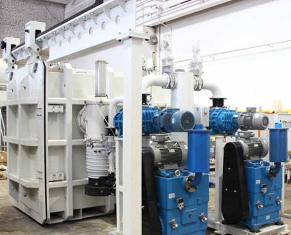
The ELU-8/0.6 unit is designed for precision electron beam welding of circular, ring, and straight seams on products made of high-strength steels and alloys based on nickel, titanium, niobium, molybdenum, copper, aluminum, as well as dissimilar metallic materials.
Unit composition:
- Operating chamber.
- Electron beam gun manipulator.
- Machine complex.
- Vacuum system.
- Pneumatic system.
- Water cooling system.
- Electrical wiring.
- Power unit.
- Operator's workplace.
- Technologist's workplace.
- Control system.
Operating chamber.
The vacuum chamber is a welded structure of rectangular cross-section.
The following mechanisms and devices are located inside the chamber:
Machine complex;
- loading platform;
- electron beam gun manipulator;
- electron beam gun;
- observation system units with devices for protecting optics from deposition;
− Intra-chamber illumination.
The vacuum part of the chamber is made of non-magnetic stainless steel.
The chamber walls provide the necessary strength and stability of the chamber, guaranteeing its operation without breaking the tightness and geometric dimensions for at least 10 years of continuous operation. To meet the requirements of rigidity and stability, the chamber walls are made with the necessary lathing or have a honeycomb structure.
The flanges on the rear wall of the chamber connect with the vacuum system. 4 light lanterns on the ceiling of the chamber illuminate the chamber inside. The frame is rolled in/out, with the machine complex installed on it via guides placed inside the chamber. The clamps with pneumatic cylinders do fix the sliding cover on the sides of the chamber.
Six inspection hatches ensure easy of observation and visual control of the welding process.
The design of the chamber and inspection hatches provides a protection for the operator from X-ray radiation. Protection against spraying, X-ray and thermal radiation of portholes, sealed entries into the chamber, cables, mechanisms and devices located inside the chamber is provided taking into account the power of the power unit.
Electron beam gun manipulator.
The electron beam gun (EB) manipulator is designed to position the EB relative to the welded product, as well as to move it during welding.
The movement electric motors are located directly on the manipulator units and ensure stable operation in a vacuum over the entire speed range.
Guides, motors, gears are reliably protected from splashes and vapors of molten metal.
Machine complex.
The parameters and configuration of the machine complex are selected at the design stage for specific tasks in agreement with the customer.
The machine complex is a transport module with two rotators installed on it alternately: with a horizontal axis of rotation (HRO) and with a vertical axis of rotation (VRO).
The HRO and VRO rotators are designed to secure and rotate welded parts with assembly and welding equipment, at a speed of 0.02 to 6 rpm, with smooth adjustment over the entire speed range.
The HRO and VRO rotators ensure smooth and uniform rotation of the welded product over the entire range of compression force of the welded parts. The parts of the HRO and VRO rotators are made of non-magnetic materials.
The VRO rotator is equipped with a faceplate. A three-jaw machine chuck is installed on the HRO rotator. The HRO is equipped with a removable rear rotating center for axial compression of parts. The table on which the tailstock and headstock are located must have central and peripheral grooves for their mutual movement.
The HRO kit includes two supporting roller supports for centering the middle part of the welded assemblies.
The transport module is pulled out of the operating chamber along special guides. The transport module is fixed in the operating chamber and on the platform.
Loading platform.
The loading platform is designed for loading and unloading welded parts with assembly and welding equipment onto the machine complex, and organizing transport movements of the welding manipulator to the operating chamber and back.
The platform has guides which are an extension of the guides inside the operating chamber. The length of the guides ensures full extension of the welding manipulator from the operating chamber.
The platform has a rigid connection with the vacuum chamber to prevent displacement of the guides during operation of the unit. To ensure support of the loading platform in the extended state a base with a rail track located on the same axis with the rail track of the operating chamber and additional rollers on the loading platform are provided. To ensure the safety of the electron beam gun during loading and unloading of products the design ensures that the electron beam gun does not protrude beyond the boundaries of the operating chamber when the loading platform is extended out.
Sliding lid.
The sliding lid is made of stainless steel with a processed flange edging along the perimeter. Vacuum seals are installed along the perimeter on the processed surface in places where they adjoin the chamber flange. In order to ensure the safety of the work and maximum access to the product, the operating chamber lid is made in a design that ensures its sideways movement, regardless of the loading platform, perpendicular to its axis.
The supports are designed for installation and fastening of the vacuum chamber. The supports are attached to the foundation with anchor bolts. The support is a welded structure.
The rail track consists of two sections connected to each other and is used for installation and movement along the guides of the sliding cover. The sections are two longitudinal pipes made of a square profile, connected to each other by the same pipes, guides are installed on top of the profile pipe.
The length of the service platform and its fence is made according to the size of the length of the operating chamber.
Vacuum system.
The vacuum system is designed to create a vacuum inside the chamber to a degree of vacuum of 1 * 10-4 mm Hg (1.3 * 10-2 Pa) and consists of three lines: a forevacuum and two high-vacuum lines. Forevacuum pumping is performed by mechanical vacuum pumps. High-vacuum pumping in the chamber to a degree of vacuum of 1 * 10-4 mm Hg is performed by steam-oil diffusion pumps. The vacuum level of 5 * 10-5 mm Hg (6.6 * 10-3 Pa) in the electron beam gun is achieved by pumping with a turbomolecular pump. The valves of the vacuum system are equipped with pneumatic cylinders. The vacuum in the chamber is controlled by a wide-range vacuum gauge. The vacuum system is controlled from the central operator panel, both in automatic and manual modes. To prevent oil vapor from entering the chamber, water-cooled traps are installed in front of the diffusion pumps. The exhaust of the forevacuum pumps is carried out through oil separators.
Pneumatic system.
The pneumatic system is designed to supply compressed air to the door clamp pneumatic cylinders, as well as to the pneumatic cylinders of the valves and shutters of the vacuum system of the unit. The operation of the vacuum system is controlled by pneumatic distributors located on the pneumatic cylinders of the vacuum valves. The clamping and squeezing of the sliding cover is also carried out through the pneumatic distributor. An air preparation unit is used to prepare compressed air.
Water cooling system.
The water cooling system of the unit is autonomous, closed from the industrial cooler (chiller), designed to cool the vacuum pumps, traps, and the electron beam gun. The cooling liquid is distributed through a pressure-drain manifold equipped with temperature sensors, water flow sensors, and a pressure sensor. An alarm signal appears when no water at the drain.
Distilled or specially prepared water must use as a coolant To prevent salt deposits and corrosion on the walls of the jackets and channels of the cooled devices.
Electrical wiring.
The internal electrical wiring is designed to provide power supply from the sealed leads to the drives of the machine tool complex actuators and the electron beam gun and the microswitches of the movement mechanisms.
External electrical wiring is intended for supplying power circuits to the power source, control cabinet, sliding cover electric motor, vacuum and pneumatic system elements, for supplying control circuits to control panels, microswitches and water cooling and lighting system elements. Electrical wiring uses shielded cables, protective boxes and cable channels.
Power unit.
The technological complex includes a power unit consisting of:
- Electron beam gun with indirectly heated cathode made of LaB6;
- Turbomolecular pump;
- High-voltage power source 60 kV, 40 kW;
- Control rack;
- Video monitoring device.
Operator's workplace.
The operator's workplace has a control panel that moves along the chamber which allows the operator to simultaneously work on the panel and observe through the portholes.
The control panel contains the control and the operator panel of the control system, and the video surveillance system monitor.
The operator's panel contains controls and indicators that allow to control the actuators of the mechanical and vacuum systems, the main parameters of the electron beam unit, set the control modes of the unit, etc.
The operator's panel contains a video monitor on the screen, which displays the current phase of the technological process, the operating modes of the control system, the main monitored parameters, emergency messages, etc.
The image of the welding zone is displayed on the screen of the video surveillance system monitor.
An additional remote control is located near the sliding door of the operating chamber to control the chamber door, the movement of the transport module from the chamber to the loading platform and back, the adjustment movements of the welding manipulator and the EBP manipulator.
The unit is serviced from the service platform.
Workplace of the technologist.
The workplace of the technologist includes a table with a personal computer, printer and monitor, for preparing and editing programs, documenting the welding process, analyzing oscillograms of the controlled welding parameters.
The workplace of the technologist is located directly next to the technological complex or in a separate room (no further than 50 m).
Control system of the automated electron-beam technological complex (CS AELTC).
The control system is designed to control:
- vacuum system;
- mechanical system;
- electron-beam unit;
in the modes:
- manual control (adjustment);
- automatic control according to a given program;
The unit is controlled from the operator's workplace.
The control system ensures automatic adjustment of sharp focusing.
Welding zone monitoring system.
The welding zone is monitored both directly through the portholes and on the video monitor.
There are two types of monitoring systems:
- a system based on image creation by means of a video camera;
- a system based on image creation by scanning the joint zone with an electron beam and synchronous recording of the signal from the secondary electron collector.
The video camera-based system ensures:
− clear image of the welding zone on the video monitor screen when adjusting for a joint or inspecting the weld after welding;
− changing the image size on the screen from 2 to 10 times for the purpose of precise beam adjustment to the joint of the welded part and panoramic inspection of the welding site;
− the optical channel of the video camera is reliably protected from extraneous illumination, spraying and splashes during metal evaporation during welding;
− the video camera is controlled from the control panel of the process complex.
The system based on secondary electrons is part of the power unit and is called a video control device (VCD).
The joint search system ensures alignment of the beam with the joint of the parts being welded.
The joint trajectory is recorded semi-automatically:
1. The operator manually aligns the beam (with a probe current value of about 0.2–1 mA) with the joint at a number of points along the entire joint trajectory, the number of which is specified in the control program.
2. Alignment of the beam with the joint trajectory can be accomplished either by deflecting the beam or by moving the gun manipulator
3. A table with the required beam or manipulator deflection values for aligning the beam with the joint at specified points along the joint trajectory is generated in the control system memory.
After recording the trajectory, the welding control program is processed at the stages of tacking, welding, cosmetics, etc. with automatic alignment of the beam with the previously defined joint trajectory.
This method is applicable to assemblies that do not experience joint trajectory deformation during welding of more than 0.3 mm.
The system for determining the sharp focus automatically adjusts the sharp focus by secondary (reflected) electrons.
The system for documenting the results of control program execution monitoring.
The goal is to create a welding process passport for a specific assembly - an electronic document (file) that records the parameters of the welding process performed during the execution of the control program.
The passport allows determining the compliance of the process performed with the standard (approved) welding process.
The system is based on the data obtained during the monitoring of the program execution.
When the control program execution is completed, the control system transmits the monitoring data to the personal computer of the technologist's workplace.
The operator prints out the welding process passport for this assembly, which indicates the identifiers of the program, assembly, operator, CNC, date, and start time of recording.
The following are subject to mandatory registration:
- welding current (beam current);
− accelerating voltage value;
− focusing coil current;
− vacuum value in the chamber and gun.
The final form of the document and the volume of data provided in it are determined by agreement with the "Customer" during the trial operation of the system.
Unit composition:
- Operating chamber.
- Electron beam gun manipulator.
- Machine complex.
- Vacuum system.
- Pneumatic system.
- Water cooling system.
- Electrical wiring.
- Power unit.
- Operator's workplace.
- Technologist's workplace.
- Control system.
Operating chamber.
The vacuum chamber is a welded structure of rectangular cross-section.
The following mechanisms and devices are located inside the chamber:
Machine complex;
- loading platform;
- electron beam gun manipulator;
- electron beam gun;
- observation system units with devices for protecting optics from deposition;
− Intra-chamber illumination.
The vacuum part of the chamber is made of non-magnetic stainless steel.
The chamber walls provide the necessary strength and stability of the chamber, guaranteeing its operation without breaking the tightness and geometric dimensions for at least 10 years of continuous operation. To meet the requirements of rigidity and stability, the chamber walls are made with the necessary lathing or have a honeycomb structure.
The flanges on the rear wall of the chamber connect with the vacuum system. 4 light lanterns on the ceiling of the chamber illuminate the chamber inside. The frame is rolled in/out, with the machine complex installed on it via guides placed inside the chamber. The clamps with pneumatic cylinders do fix the sliding cover on the sides of the chamber.
Six inspection hatches ensure easy of observation and visual control of the welding process.
The design of the chamber and inspection hatches provides a protection for the operator from X-ray radiation. Protection against spraying, X-ray and thermal radiation of portholes, sealed entries into the chamber, cables, mechanisms and devices located inside the chamber is provided taking into account the power of the power unit.
Electron beam gun manipulator.
The electron beam gun (EB) manipulator is designed to position the EB relative to the welded product, as well as to move it during welding.
The movement electric motors are located directly on the manipulator units and ensure stable operation in a vacuum over the entire speed range.
Guides, motors, gears are reliably protected from splashes and vapors of molten metal.
Machine complex.
The parameters and configuration of the machine complex are selected at the design stage for specific tasks in agreement with the customer.
The machine complex is a transport module with two rotators installed on it alternately: with a horizontal axis of rotation (HRO) and with a vertical axis of rotation (VRO).
The HRO and VRO rotators are designed to secure and rotate welded parts with assembly and welding equipment, at a speed of 0.02 to 6 rpm, with smooth adjustment over the entire speed range.
The HRO and VRO rotators ensure smooth and uniform rotation of the welded product over the entire range of compression force of the welded parts. The parts of the HRO and VRO rotators are made of non-magnetic materials.
The VRO rotator is equipped with a faceplate. A three-jaw machine chuck is installed on the HRO rotator. The HRO is equipped with a removable rear rotating center for axial compression of parts. The table on which the tailstock and headstock are located must have central and peripheral grooves for their mutual movement.
The HRO kit includes two supporting roller supports for centering the middle part of the welded assemblies.
The transport module is pulled out of the operating chamber along special guides. The transport module is fixed in the operating chamber and on the platform.
Loading platform.
The loading platform is designed for loading and unloading welded parts with assembly and welding equipment onto the machine complex, and organizing transport movements of the welding manipulator to the operating chamber and back.
The platform has guides which are an extension of the guides inside the operating chamber. The length of the guides ensures full extension of the welding manipulator from the operating chamber.
The platform has a rigid connection with the vacuum chamber to prevent displacement of the guides during operation of the unit. To ensure support of the loading platform in the extended state a base with a rail track located on the same axis with the rail track of the operating chamber and additional rollers on the loading platform are provided. To ensure the safety of the electron beam gun during loading and unloading of products the design ensures that the electron beam gun does not protrude beyond the boundaries of the operating chamber when the loading platform is extended out.
Sliding lid.
The sliding lid is made of stainless steel with a processed flange edging along the perimeter. Vacuum seals are installed along the perimeter on the processed surface in places where they adjoin the chamber flange. In order to ensure the safety of the work and maximum access to the product, the operating chamber lid is made in a design that ensures its sideways movement, regardless of the loading platform, perpendicular to its axis.
The supports are designed for installation and fastening of the vacuum chamber. The supports are attached to the foundation with anchor bolts. The support is a welded structure.
The rail track consists of two sections connected to each other and is used for installation and movement along the guides of the sliding cover. The sections are two longitudinal pipes made of a square profile, connected to each other by the same pipes, guides are installed on top of the profile pipe.
The length of the service platform and its fence is made according to the size of the length of the operating chamber.
Vacuum system.
The vacuum system is designed to create a vacuum inside the chamber to a degree of vacuum of 1 * 10-4 mm Hg (1.3 * 10-2 Pa) and consists of three lines: a forevacuum and two high-vacuum lines. Forevacuum pumping is performed by mechanical vacuum pumps. High-vacuum pumping in the chamber to a degree of vacuum of 1 * 10-4 mm Hg is performed by steam-oil diffusion pumps. The vacuum level of 5 * 10-5 mm Hg (6.6 * 10-3 Pa) in the electron beam gun is achieved by pumping with a turbomolecular pump. The valves of the vacuum system are equipped with pneumatic cylinders. The vacuum in the chamber is controlled by a wide-range vacuum gauge. The vacuum system is controlled from the central operator panel, both in automatic and manual modes. To prevent oil vapor from entering the chamber, water-cooled traps are installed in front of the diffusion pumps. The exhaust of the forevacuum pumps is carried out through oil separators.
Pneumatic system.
The pneumatic system is designed to supply compressed air to the door clamp pneumatic cylinders, as well as to the pneumatic cylinders of the valves and shutters of the vacuum system of the unit. The operation of the vacuum system is controlled by pneumatic distributors located on the pneumatic cylinders of the vacuum valves. The clamping and squeezing of the sliding cover is also carried out through the pneumatic distributor. An air preparation unit is used to prepare compressed air.
Water cooling system.
The water cooling system of the unit is autonomous, closed from the industrial cooler (chiller), designed to cool the vacuum pumps, traps, and the electron beam gun. The cooling liquid is distributed through a pressure-drain manifold equipped with temperature sensors, water flow sensors, and a pressure sensor. An alarm signal appears when no water at the drain.
Distilled or specially prepared water must use as a coolant To prevent salt deposits and corrosion on the walls of the jackets and channels of the cooled devices.
Electrical wiring.
The internal electrical wiring is designed to provide power supply from the sealed leads to the drives of the machine tool complex actuators and the electron beam gun and the microswitches of the movement mechanisms.
External electrical wiring is intended for supplying power circuits to the power source, control cabinet, sliding cover electric motor, vacuum and pneumatic system elements, for supplying control circuits to control panels, microswitches and water cooling and lighting system elements. Electrical wiring uses shielded cables, protective boxes and cable channels.
Power unit.
The technological complex includes a power unit consisting of:
- Electron beam gun with indirectly heated cathode made of LaB6;
- Turbomolecular pump;
- High-voltage power source 60 kV, 40 kW;
- Control rack;
- Video monitoring device.
Operator's workplace.
The operator's workplace has a control panel that moves along the chamber which allows the operator to simultaneously work on the panel and observe through the portholes.
The control panel contains the control and the operator panel of the control system, and the video surveillance system monitor.
The operator's panel contains controls and indicators that allow to control the actuators of the mechanical and vacuum systems, the main parameters of the electron beam unit, set the control modes of the unit, etc.
The operator's panel contains a video monitor on the screen, which displays the current phase of the technological process, the operating modes of the control system, the main monitored parameters, emergency messages, etc.
The image of the welding zone is displayed on the screen of the video surveillance system monitor.
An additional remote control is located near the sliding door of the operating chamber to control the chamber door, the movement of the transport module from the chamber to the loading platform and back, the adjustment movements of the welding manipulator and the EBP manipulator.
The unit is serviced from the service platform.
Workplace of the technologist.
The workplace of the technologist includes a table with a personal computer, printer and monitor, for preparing and editing programs, documenting the welding process, analyzing oscillograms of the controlled welding parameters.
The workplace of the technologist is located directly next to the technological complex or in a separate room (no further than 50 m).
Control system of the automated electron-beam technological complex (CS AELTC).
The control system is designed to control:
- vacuum system;
- mechanical system;
- electron-beam unit;
in the modes:
- manual control (adjustment);
- automatic control according to a given program;
The unit is controlled from the operator's workplace.
The control system ensures automatic adjustment of sharp focusing.
Welding zone monitoring system.
The welding zone is monitored both directly through the portholes and on the video monitor.
There are two types of monitoring systems:
- a system based on image creation by means of a video camera;
- a system based on image creation by scanning the joint zone with an electron beam and synchronous recording of the signal from the secondary electron collector.
The video camera-based system ensures:
− clear image of the welding zone on the video monitor screen when adjusting for a joint or inspecting the weld after welding;
− changing the image size on the screen from 2 to 10 times for the purpose of precise beam adjustment to the joint of the welded part and panoramic inspection of the welding site;
− the optical channel of the video camera is reliably protected from extraneous illumination, spraying and splashes during metal evaporation during welding;
− the video camera is controlled from the control panel of the process complex.
The system based on secondary electrons is part of the power unit and is called a video control device (VCD).
The joint search system ensures alignment of the beam with the joint of the parts being welded.
The joint trajectory is recorded semi-automatically:
1. The operator manually aligns the beam (with a probe current value of about 0.2–1 mA) with the joint at a number of points along the entire joint trajectory, the number of which is specified in the control program.
2. Alignment of the beam with the joint trajectory can be accomplished either by deflecting the beam or by moving the gun manipulator
3. A table with the required beam or manipulator deflection values for aligning the beam with the joint at specified points along the joint trajectory is generated in the control system memory.
After recording the trajectory, the welding control program is processed at the stages of tacking, welding, cosmetics, etc. with automatic alignment of the beam with the previously defined joint trajectory.
This method is applicable to assemblies that do not experience joint trajectory deformation during welding of more than 0.3 mm.
The system for determining the sharp focus automatically adjusts the sharp focus by secondary (reflected) electrons.
The system for documenting the results of control program execution monitoring.
The goal is to create a welding process passport for a specific assembly - an electronic document (file) that records the parameters of the welding process performed during the execution of the control program.
The passport allows determining the compliance of the process performed with the standard (approved) welding process.
The system is based on the data obtained during the monitoring of the program execution.
When the control program execution is completed, the control system transmits the monitoring data to the personal computer of the technologist's workplace.
The operator prints out the welding process passport for this assembly, which indicates the identifiers of the program, assembly, operator, CNC, date, and start time of recording.
The following are subject to mandatory registration:
- welding current (beam current);
− accelerating voltage value;
− focusing coil current;
− vacuum value in the chamber and gun.
The final form of the document and the volume of data provided in it are determined by agreement with the "Customer" during the trial operation of the system.
Technical data
Operational volume of the vacuum chamber, m3
11.6
Inner dimensions of the chamber (L*W*H), mm
3100*1700*2200
Power consumption, kW
120
Load capacity of rotation manipulators with horizontal axis, kg
1000
Load capacity of rotation manipulators with a vertical axis, kg
1000
Dimensions of welded products with a horizontal axis of rotation (Ø*D), mm
(40 - 400)*1500
Dimensions of welded products on a manipulator with a vertical axis of rotation (with a vertical gun position) (Ø*D), mm
(≤400)*(≤500)
Dimensions of welded products on a manipulator with a vertical axis of rotation (with a horizontal gun position) (Ø*D), mm
(≤300)*(≤500)
Operating pressure in the chamber, Pa (mm Hg)
1.3*10-2 (1*10-4)
Operating pressure in the electron beam gun, Pa (mm Hg)
6.6*10-3 (5*10-5)
Time to reach operating pressure in the vacuum chamber and electron beam gun during repeated pumping, minutes
30
Visualization of the junction area
Video monitoring device
Method of combining a beam with a joint
Recording the trajectory by points, then automatically aligning the beam with the joint by deflecting the beam or moving the gun
Overall dimensions of the installation (L*W*H), mm
10700*6750*3000
Range of electron beam current, mA
1 - 660
Accelerating voltage instability, %
±0.5
Focusing lens current instability, %
±0.05
Range of focusing current, mA
400 - 1000
Distance between gun and workpiece, mm
50 - 259
Maximal deflection angle along the X-X and Y-Y axes of the deflection system, °
±7
Maximal power consumption of equipment, kVA
120
Electron beam gun accelerating voltage, kV
60
Resulting image size, pixels
256*256
Size of the observed area of the product, at a distance from the bottom edge of the EB gun to the product, mm
20*20
Rated voltage of three-phase supply network 50 Hz, V
400
Controlled coordinates of movement of the welding manipulator
1 (A or C)
Controlled moving coordinates of the electron gun moving manipulator
3 (x, y, z)
Number of simultaneously controlled coordinates
4 (X, Y, Z, A or C)
The movement of the electron gun manipulator longitudinal (X), mm
1200
The magnitude of the transverse movements of the electron gun manipulator (Y), mm
400
The movement of the electron gun manipulator vertical (Z), mm 800
800
The movement of the electron gun manipulator, adjustment rotation (XZ), °
0 – 90
Detailed information PDF
Submit an inquiry
Прошлое
Настоящее
Будущее